


TANK-760 Em b e d d e d S ys te m
P a g e i
Us e r Ma n u a l
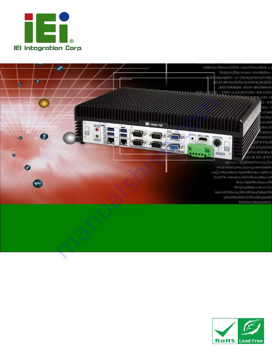
MODEL:
TANK-760
Hig h P e rfo rm a n c e Fa n le s s Em b e d d e d S ys te m with In te l® Co re i5-4400E/
Ce le ro n 2000E p ro c e s s o r, VGA, HDMI, Dis p la yP o rt,
9-36V DC in p u t a n d Ro HS Co m p lia n t
Re v. 1.01 – 5 De c e m b e r 2014
Summary of Contents for TANK-760
Page 8: ...TANK 760 Embedded Sys tem Page viii Figure 3 26 Power Button 35 ...
Page 10: ...TANK 760 Embedded Sys tem Page 1 Chapter 1 1 Introduction ...
Page 19: ...TANK 760 Embedded Sys tem Page 10 Chapter 2 2 Unpacking ...
Page 23: ...TANK 760 Embedded Sys tem Page 14 Chapter 3 3 Ins tallation ...
Page 45: ...TANK 760 Embedded Sys tem Page 36 Chapter 4 4 BIOS ...
Page 81: ...TANK 760 Embedded Sys tem Page 72 Appendix A A Safety Precautions ...
Page 86: ...TANK 760 Embedded Sys tem Page 77 Appendix B B Hazardous Materials Dis clos ure ...


