


TANK -720 E mbedded S ys tem
P age i
Us er Manual
MODE L :
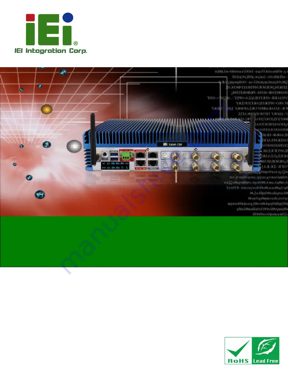
TANK -720
High P erformance F anles s E mbedded S ys tem with
2nd G en Intel® C ore™ i7/i5/i3, C eleron® and P entium® des ktop proces s ors ,
On-board 2.0 G B DDR 3 Memory, VG A/HDMI, US B 3.0, Dual C ombo (S F P
F iber/R J -45) G igabit L AN, Is olated C AN-bus , Audio and R oHS C ompliant
R ev. 2.02 – 7 March 2018
Summary of Contents for TANK-720
Page 9: ...TANK 720 E mbedded S ys tem Page ix E HAZARDOUS MATERIALS DISCLOSURE 103 ...
Page 14: ...TANK 720 E mbedded S ys tem Page 1 Chapter 1 1 Introduction ...
Page 23: ...TANK 720 E mbedded S ys tem Page 10 Chapter 2 2 Unpacking ...
Page 28: ...TANK 720 E mbedded S ys tem Page 15 Chapter 3 3 Ins tallation ...
Page 39: ...TANK 720 E mbedded S ys tem Page 26 Figure 3 13 AT ATX Power Mode Switch ...
Page 61: ...TANK 720 E mbedded S ys tem Page 48 Chapter 4 4 B IOS ...
Page 99: ...TANK 720 E mbedded S ys tem Page 86 Appendix A A R egulatory Compliance ...
Page 105: ...TANK 720 E mbedded S ys tem Page 92 Appendix B B B IOS Options ...
Page 108: ...TANK 720 E mbedded S ys tem Page 95 Appendix C C S afety Precautions ...
Page 113: ...TANK 720 E mbedded S ys tem Page 100 Appendix D D Digital I O Interface ...
Page 116: ...TANK 720 E mbedded S ys tem Page 103 Appendix E E Hazardous Materials Dis clos ure ...


