


TANK-700-QM67W-MRAY Em b e d d e d S ys te m
P a g e i
Us e r Ma n u a l
MODEL:
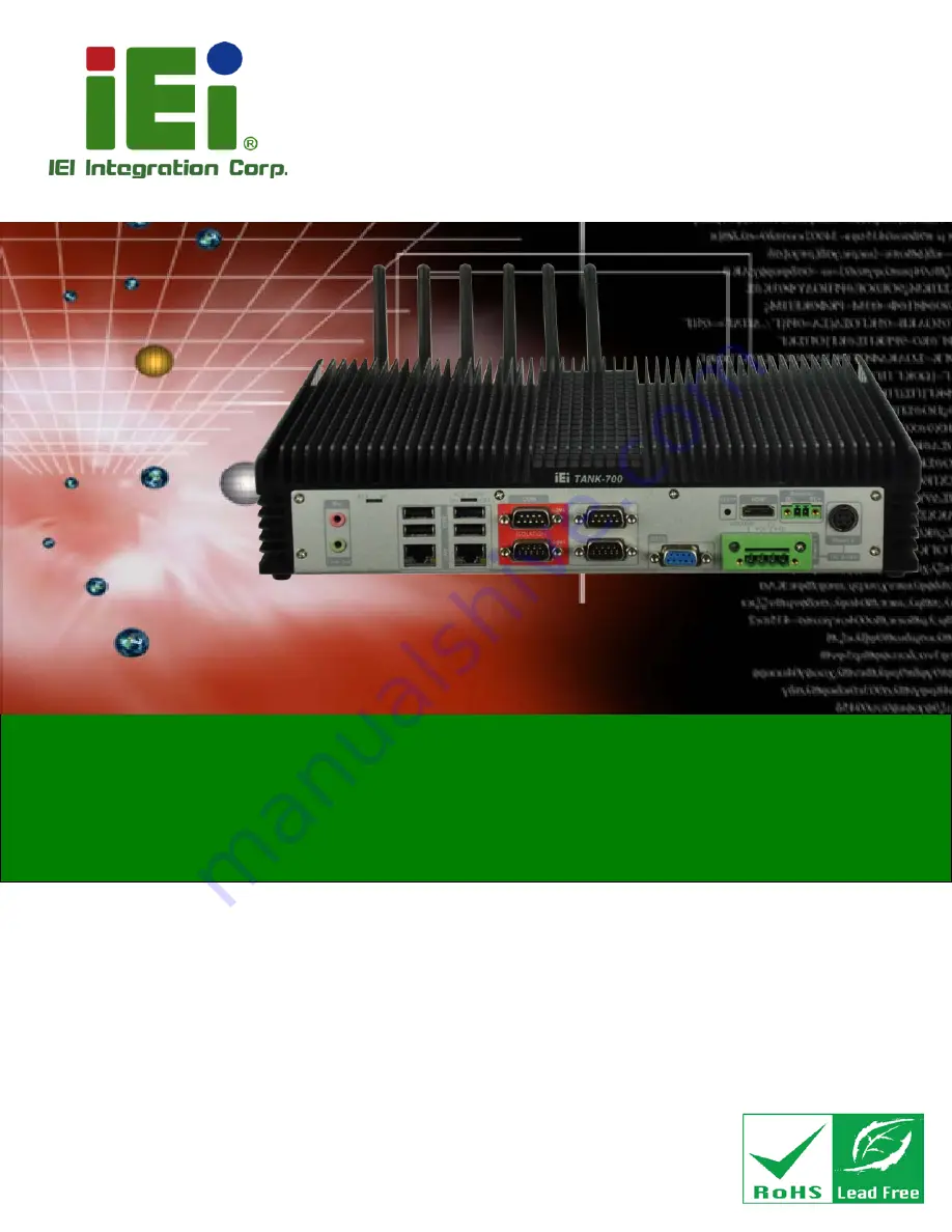
TANK-700-QM67W-MRAY
Hig h P e rfo rm a n c e Fa n le s s Em b e d d e d S ys te m with In te l® 32n m CP U,
On -b o a rd 2.0 GB DDR3 Me m o ry, HDMI, US B 3.0, Gig a b it LAN,
Au d io , 9V~36V DC In p u t, Ro HS Co m p lia n t
Re v. 1.00 – 25 No ve m b e r, 2014
Summary of Contents for TANK-700-QM67W-MRAY
Page 10: ...TANK 700 QM67W MRAY Embedded Sys tem Page 1 Chapter 1 1 Introduction ...
Page 18: ...TANK 700 QM67W MRAY Embedded Sys tem Page 9 Chapter 2 2 Unpacking ...
Page 22: ...TANK 700 QM67W MRAY Embedded Sys tem Page 13 Chapter 3 3 Ins tallation ...
Page 52: ...TANK 700 QM67W MRAY Embedded Sys tem Page 43 Chapter 4 4 BIOS ...
Page 88: ...TANK 700 QM67W MRAY Embedded Sys tem Page 79 Appendix A A Safety Precautions ...
Page 93: ...TANK 700 QM67W MRAY Embedded Sys tem Page 84 Appendix B B Hazardous Materials Dis clos ure ...


