PPC-F06B-BT Panel PC
Page I
User Manual
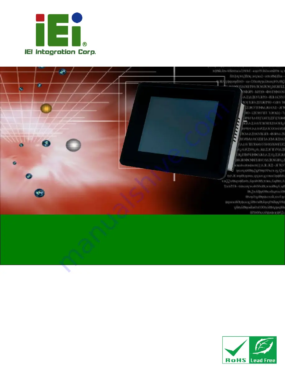
PPC-F06B-BT Panel PC
MODEL:
PPC-F06B-BT
Industrial Panel PC with Intel® Celeron® Processor N2807,
Touchscreen, PCIe Mini, USB 3.0, USB 2.0, RS-232,
RS-422/485, Dual PCIe GbE, 9 V ~ 30 V DC-in
IP 65 Compliant Front Panel and RoHS Compliant
Rev. 1.03 – December 13, 2017
Summary of Contents for PPC-F06B-BT
Page 13: ...PPC F06B BT Panel PC Page 1 1 Introduction Chapter 1 ...
Page 18: ...PPC F06B BT Panel PC Page 6 1 7 Dimensions Figure 1 6 PPC F06B BT Dimensions mm ...
Page 21: ...PPC F06B BT Panel PC Page 9 2 Unpacking Chapter 2 ...
Page 25: ...PPC F06B BT Panel PC Page 13 3 Installation Chapter 3 ...
Page 52: ...PPC F06B BT Panel PC Page 40 4 BIOS Setup Chapter 4 ...
Page 80: ...PPC F06B BT Panel PC Page 68 5 Interface Connectors Chapter 5 ...
Page 92: ...PPC F06B BT Panel PC Page 80 Appendix A A Regulatory Compliance ...
Page 98: ...PPC F06B BT Panel PC Page 86 B BIOS Configuration Options Appendix B ...
Page 101: ...PPC F06B BT Panel PC Page 89 C Safety Precautions Appendix C ...
Page 107: ...PPC F06B BT Panel PC Page 95 D Watchdog Timer Appendix D ...
Page 110: ...PPC F06B BT Panel PC Page 98 Appendix E E Hazardous Materials Disclosure ...