2012/3/62012/3/6
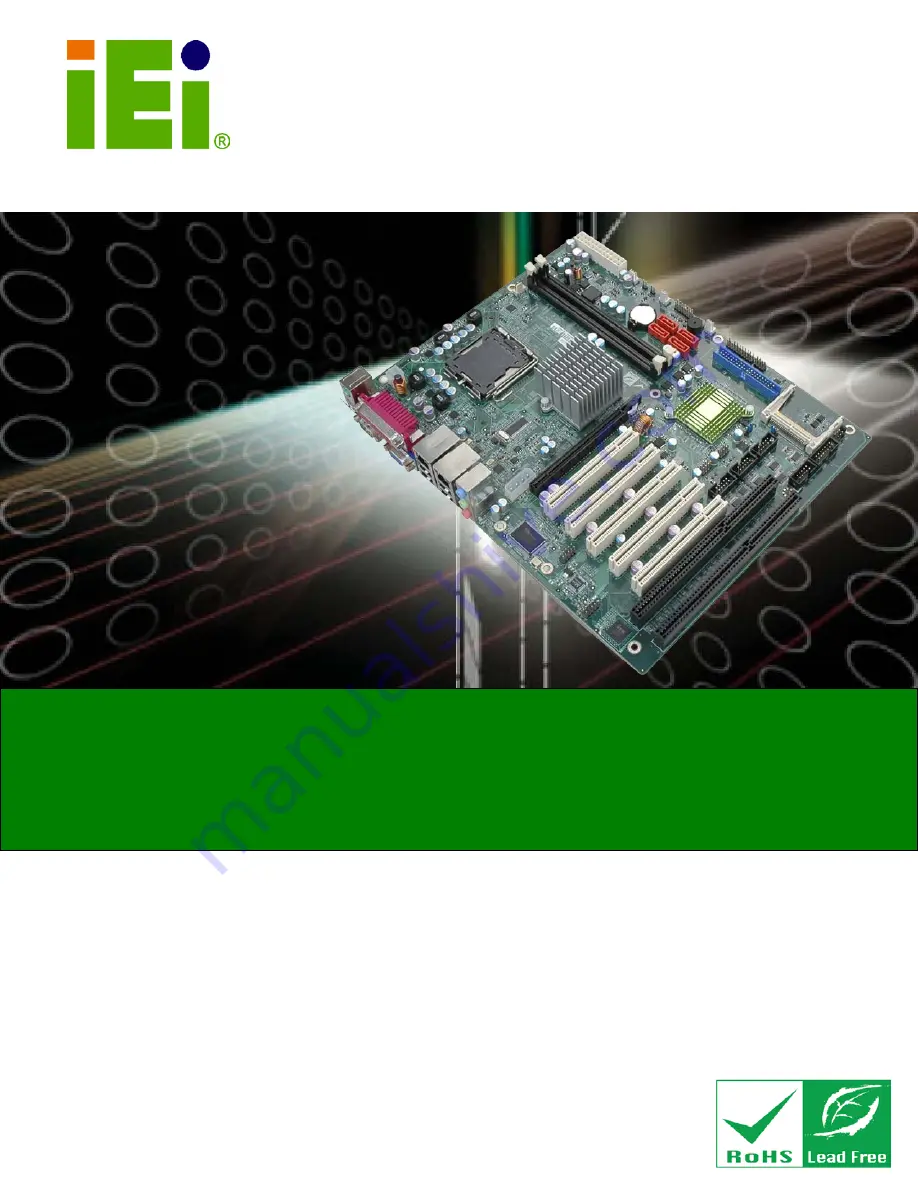
IMBA-G412IS A ATX Mo th e rb o a rd
P a g e i
IEI Te c h n o lo g y Co rp .
Us e r Ma n u a l
MODEL:
IMBA-G412IS A
ATX Mo th e rb o a rd fo r In te l® Co re ™2 Du o /Qu a d CP U,
800/1066/1333 MHz FS B, DDR3, VGA, LAN, S ATA 3Gb /s ,
P CIe x16, P CI, IS A, US B, HD Au d io , Ro HS Co m p lia n t
Re v. 2.00 – 6 Ma rc h , 2012
Summary of Contents for IMBA-G412ISA
Page 14: ......
Page 15: ...2012 1 202012 1 20 IMBA G412ISA ATX Motherboard Page 1 Chapter 1 1 Introduction ...
Page 24: ...101 20 2012164 Page 10 IMBA G412ISA ATX Motherboard Chapter 2 2 Packing Lis t ...
Page 29: ...2012 1 202012 1 20 IMBA G412ISA ATX Motherboard Page 15 Chapter 3 3 Connectors ...
Page 55: ...2012 1 202012 1 20 IMBA G412ISA ATX Motherboard Page 41 Chapter 4 4 Ins tallation ...
Page 80: ...661 20 2012164 Page 66 IMBA G412ISA ATX Motherboard Chapter 5 5 BIOS ...
Page 120: ...1061 20 2012164 Page 106 IMBA G412ISA ATX Motherboard Appendix A A BIOS Options ...
Page 124: ...1101 20 2012164 Page 110 IMBA G412ISA ATX Motherboard Appendix B B Terminology ...
Page 128: ...1141 20 2012164 Page 114 IMBA G412ISA ATX Motherboard Appendix C C One Key Recovery ...
Page 156: ...1421 20 2012164 Page 142 IMBA G412ISA ATX Motherboard Appendix D D Watchdog Timer ...
Page 159: ...2012 1 202012 1 20 IMBA G412ISA ATX Motherboard Page 145 Appendix E E Digital I O Interface ...