


ECN-360A-HM65 Em b e d d e d S ys te m
P a g e i
IEI Te c h n o lo g y Co rp .
Us e r Ma n u a l
,
MODEL:
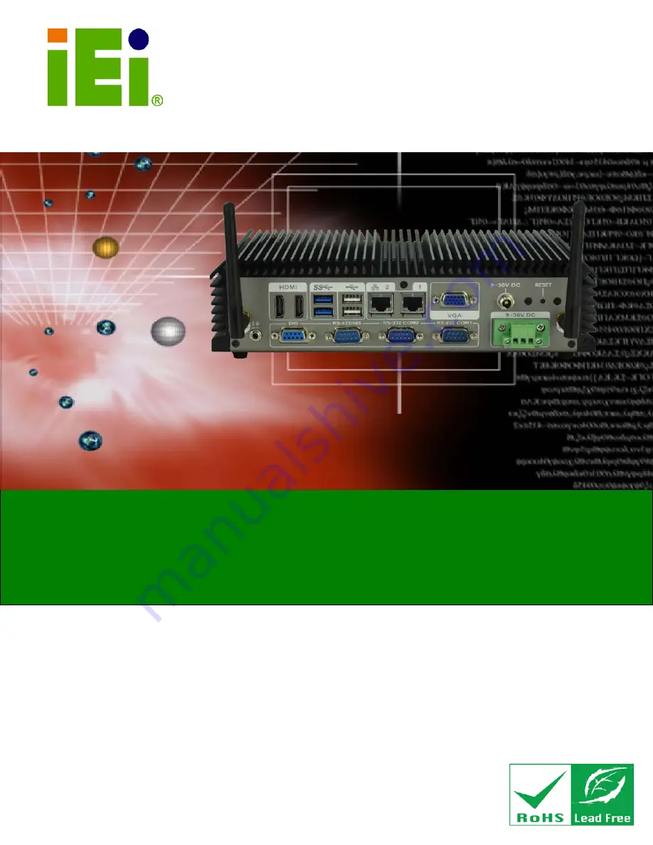
ECN-360A-HM65
Em b e d d e d S ys te m with In te l® Ce le ro n ® d u a l c o re 847E P ro c e s s o r,
Du a l HDMI, VGA, Gb E, Two US B 3.0, Two US B 2.0,
Th re e COM a n d Ro HS Co m p lia n t
Re v. 1.00 – 25 J u n e 2013
Summary of Contents for ECN-360A-HM65
Page 8: ...ECN 360A HM65 Embedded Sys tem Page viii ROHS COMPLIANT UNDER 2002 95 EC WITHOUT MERCURY 139...
Page 14: ...ECN 360A HM65 Embedded Sys tem Page 1 Chapter 1 1 Introduction...
Page 19: ...ECN 360A HM65 Embedded Sys tem Page 6 Figure 1 3 ECN 360A HM65 Rear Panel...
Page 21: ...ECN 360A HM65 Embedded Sys tem Page 8 Chapter 2 2 Unpacking...
Page 25: ...ECN 360A HM65 Embedded Sys tem Page 12 Chapter 3 3 Ins tallation...
Page 37: ...ECN 360A HM65 Embedded Sys tem Page 24 Chapter 4 4 Sys tem Motherboard...
Page 68: ...ECN 360A HM65 Embedded Sys tem Page 55 Chapter 5 5 BIOS...
Page 99: ...ECN 360A HM65 Embedded Sys tem Page 86 A Safety Precautions Appendix A...
Page 104: ...ECN 360A HM65 Embedded Sys tem Page 91 B BIOS Menu Options Appendix B...
Page 107: ...ECN 360A HM65 Embedded Sys tem Page 94 Appendix C C One Key Recovery...
Page 115: ...ECN 360A HM65 Embedded Sys tem Page 102 Figure C 5 Partition Creation Commands...
Page 148: ...ECN 360A HM65 Embedded Sys tem Page 135 D Watchdog Timer Appendix D...
Page 151: ...ECN 360A HM65 Embedded Sys tem Page 138 Appendix E E Hazardous Materials Dis clos ure...


