


DRPC-100 Embedded System
Page i
IEI Technology Corp.
User Manual
MODEL:
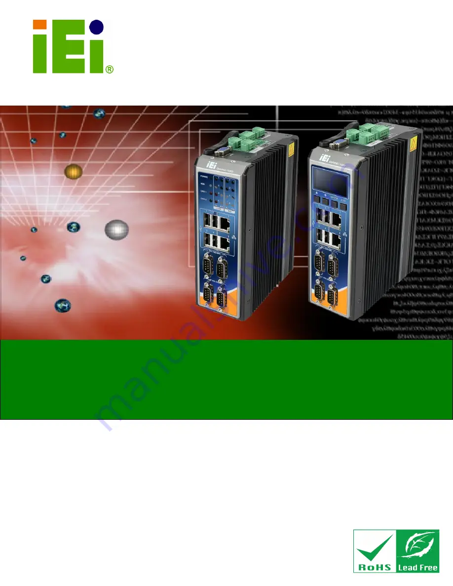
DRPC-100
Fanless Embedded System with Intel® Atom™ N2800 CPU,
DIN Rail Mounting Support, OLED Display or LED Indicators, Dual
GbE, USB, DIO, CAN-bus, Serial Ports,
9V~28V DC Power Input, RoHS Compliant
Rev. 1.01 – 22 January, 2016
Summary of Contents for DRPC-100
Page 14: ......
Page 15: ...DRPC 100 Embedded System Page 1 4Chapter 1 1 Introduction...
Page 24: ...DRPC 100 Embedded System Page 10 Chapter 2 2 Unpacking...
Page 28: ...DRPC 100 Embedded System Page 14 Chapter 3 3 Installation...
Page 51: ...DRPC 100 Embedded System Page 37 Chapter 4 4 System Maintenance...
Page 55: ...DRPC 100 Embedded System Page 41 Chapter 5 5 BIOS...
Page 84: ...DRPC 100 Embedded System Page 70 Chapter 6 6 Programmable OLED Display DRPC 100 CV OLED Only...
Page 95: ...DRPC 100 Embedded System Page 81 Chapter 7 7 Interface Connectors...
Page 107: ...DRPC 100 Embedded System Page 93 Appendix A A One Key Recovery...
Page 115: ...DRPC 100 Embedded System Page 101 Figure A 5 Partition Creation Commands...
Page 149: ...DRPC 100 Embedded System Page 135 Appendix B B Safety Precautions...
Page 154: ...DRPC 100 Embedded System Page 140 Appendix C C Digital I O Interface...
Page 157: ...DRPC 100 Embedded System Page 143 Appendix D D Hazardous Materials Disclosure...


