background image

PLEASE READ THIS MANUAL BEFORE SWITCHING THE UNIT ON.

IMPORTANT SAFETY INFORMATION INSIDE.

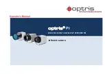
Shown with a 13 mm lens.

2105 W. Cardinal Dr. Beaumont, TX 77705

ICI cameras fall under US Federal Law and Export Control.

For more information, contact us: (409) 861-0788 | [email protected] | www.infraredcameras.com

Edit Text

Outlines

Industry

Industry

Revision: 11.2022-001

GC-76/GC-106 GAS LEAK DETECTION CORE

USER MANUAL

PLEASE READ THIS MANUAL BEFORE SWITCHING THE UNIT ON.

IMPORTANT SAFETY INFORMATION INSIDE.

Summary of Contents for GC-106

Page 1: ...77705 ICI cameras fall under US Federal Law and Export Control For more information contact us 409 861 0788 sales infraredcameras com www infraredcameras com Edit Text Out Ind Industry Revision 11 202...

Page 2: ...GC 76 GC 106 GAS LEAK DETECTION CORE USER MANUAL 2 Revision History 09 2022 001 11 2022 001 Document created GC 106 specifications added...

Page 3: ...ate 6 2 7 Scope of Application 6 2 8 Authoritative Versions 6 2 9 Training 7 Safety Information 8 Technical Specifications 10 Structure 14 5 1 Pin Layout 14 5 2 Pin Connector Interface Description 14...

Page 4: ...or written permission of Infrared Cameras Inc The documentation must not in whole or part be copied photocopied reproduced translated or transmitted to any electronic medium or machine readable form w...

Page 5: ...l and electronic equipment The crossed out wheeled bin symbol indicates that waste electrical and electronic equipment should not be discarded together with unseparated household waste but must be col...

Page 6: ...natural gas and electric power applications Monitoring for gas leaks assists in daily equipment maintenance accident prevention and environmental protection The GC 76 can be integrated into fixed mou...

Page 7: ...GC 76 GC 106 GAS LEAK DETECTION CORE USER MANUAL 7 2 9 Training To read about infrared training visit https infraredtraininginstitute com...

Page 8: ...ed incorrectly the device may be damaged Do not put holes in the device with objects Damage to the device may occur Do not hit the device with a hammer or apply strong impacts or electric shocks to it...

Page 9: ...comes warm enough for the condensation to evaporate Keep device out of reach of children This product is a precise electronic device that must be handled with care during use storage and transportatio...

Page 10: ...d 7 m to 8 5 m Frame Rate 25 Hz Humidity 5 to 95 non condensing Pixel Operability 99 Shock 80 G Vibration 6 06 G Dimensions without lens 26 mm x 26 mm x 22m L x W x D 0 5 mm 1 02 x 1 02 L x W x H 0 02...

Page 11: ...s based on tests without extension boards Typical working voltage is 4V DC Expansion boards support 3 5V 18V DC 3 The analog video output format is PAL D 4 8 Bit or 14 Bit LVCMOS digital video is supp...

Page 12: ...h 12 m Spectral Band 7 m to 8 5 m Frame Rate 25 Hz Humidity 5 to 95 non condensing Pixel Operability 99 Shock 80 G Vibration 6 06 G Dimensions without lens 26 mm x 26 mm x 22m L x W x D 0 5 mm 1 02 x...

Page 13: ...ons without expansion board 2 Wattage is based on tests without extension boards Typical working voltage is 4V DC Expansion boards support 3 5V 18V DC 3 The analog video output format is PAL D 4 8 Bit...

Page 14: ...contained on the connector Users can adopt the Hirose 70 Pin DF40HC 3 0 70DS 0 4V 51 to implement the connection between the thermal camera and user expansion boards 5 Structure 5 2 Pin Connector Inte...

Page 15: ...34 DV8 Data 35 DV11 Data 36 DV10 Data 37 DV13 Data MSB 14 bit 38 DV12 Data 24 DV14 Data Data 23 DV15 Data MSB 16 bit Data MSB BT 1120 39 Line_Valid Line valid signal Line valid signal 40 Frame_Valid F...

Page 16: ...l camera s sending and receiving 3 GND and VGND are shorted internally PLEASE READ AND UNDERSTAND THE TABLES BEFORE SWITCHING THE UNIT ON NO Name Type Description 47 LVDS_CLK Output LVDS_H VCCIO 2 5V...

Page 17: ...id frame signal Frame_Valid and 14 data signals DV0 DV13 Pixel data bits are divided into 8 bit and 14 bit When ORG or TEMP data is produced the data bits are 14 bits namely DV 13 0 where DV0 is LSB a...

Page 18: ...abled disabled by control commands When it is enabled the output of ORG data NUC data DRC data DNS data and TEMP data can be selected When choosing to use DRC data the digital zoom and temperature dis...

Page 19: ...mponent and the image supports pseudo color mapping The second half of each row is divided into temperature data The actual significant bit is 14 bits and the higher two bits complement 0 CDS_2 Clock...

Page 20: ...ITCHING THE UNIT ON 6 1 5 BT 1120 BT 1120 digital video outputs signals line by line It includes clock signals Clock frame valid signal line valid signal and 16 data signals DV0 DV15 As shown When BT...

Page 21: ...frame and exits at the end of the frame The inter frame is in the low power mode the data and clock lines are both at 1 2V high level The CLK frequency of the thermal core is 200MHz After the core is...

Page 22: ...typical 12V DC RS 232 UART BT 656 digital video Analog video 4 Keys Hirose 20 pin DF52 20S 0 8H connector Molex 20 pin 52745 2097 connector Call for information Power input 3 5V 18V DC typical 12V DC...

Page 23: ...l not clean replace the cloth and repeat operation 9 2 Disinfecting the Camera Surface Do not use corrosive cleaning solutions on the optical glass components Do not get the electronics wet It is reco...

Page 24: ...ared Training Institute In addition to providing custom germanium silica and sapphire optics we also build windows for enclosures as well as custom pan and tilt units We can even provide customizable...

Reviews: