iCanTek iCanView372, User Manual
Get the most out of your iCanTek iCanView372 with the comprehensive User Manual available for free download from manualshive.com. This detailed manual provides step-by-step instructions and troubleshooting tips to ensure you can maximize the features of your device. Don't miss out on this valuable resource.
Share
Download


Reviews:
No comments
Related manuals for iCanView372

Welcome M21311P1-A
Brand: ABB Pages: 15

WGSMSC
Brand: Watchguard Pages: 8

B2372TIR
Brand: Digital Watchdog Pages: 3

XIN-MPC-0110
Brand: Xineron Pages: 12

TSSC
Brand: ADT Pages: 9

GSD-682
Brand: Geutebruck Pages: 148

Virtuoso Series
Brand: Vitek Pages: 20

DGEMSR360P1
Brand: Diginet Pages: 16

NVIP-5H-6201
Brand: Novus Pages: 56
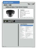
HVC-150 -
Brand: OPTICOM Pages: 1

CLEARVU11
Brand: SVAT Pages: 26

RHPC-HD10
Brand: OEM Pages: 18

WV-SW350 Series
Brand: Panaso Pages: 228

DWH SERIES
Brand: ELRO Pages: 37

BUMDV07IR
Brand: E-Vision Pages: 20

2-Zone Remote Alarm
Brand: Onset Pages: 2

CCTV-210
Brand: Steren Pages: 142

NVIP-5DN3600C-2P/F
Brand: Novus Pages: 40


