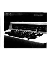
IBM Selectric, Maintenance Manual
The IBM Selectric typewriter is a classic office machine known for its reliability and durability. Ensure the longevity of your typewriter with the Maintenance Manual available for free download on manualshive.com. Keep your typewriter running smoothly with the comprehensive manual provided.
Share
Download


Reviews:
No comments
Related manuals for Selectric
KX-E2000
Brand: Panasonic Pages: 63
1830
Brand: Facit Pages: 14
C-1
Brand: IBM Pages: 57
B-1
Brand: IBM Pages: 40
900X
Brand: Olivetti Pages: 69
SM 9
Brand: Olympia Pages: 4
AE-800
Brand: Nakajima Pages: 42
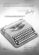
Hermes Baby
Brand: Paillard Pages: 6
6 - Lexmark Wheelwriter 6 Professional...
Brand: IBM Pages: 94
Selectric Personal Typewriter
Brand: IBM Pages: 45
6747
Brand: IBM Pages: 82
Wheelwriter 10 - IBM Wheelwriter 10 Professional...
Brand: IBM Pages: 54

TYPECAST
Brand: We R memory keepers Pages: 14
Letterwriter 100
Brand: Digital Equipment Pages: 60
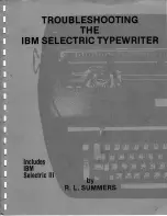
Selectric III
Brand: IBM Pages: 199
Selectric III - Correcting Selectric III
Brand: IBM Pages: 30
WPT-150
Brand: Nakajima Pages: 17

Flexowriter
Brand: Friden Pages: 500


