


Welcome. . .
This
contains information for
setting up, configuring, and
using your BladeCenter T unit.
For detailed information about
your BladeCenter T unit, view
the publications on the
You can also find the most
current information about your
BladeCenter T unit and servers
on the IBM Web site at:
http://www.ibm.com/pc/support
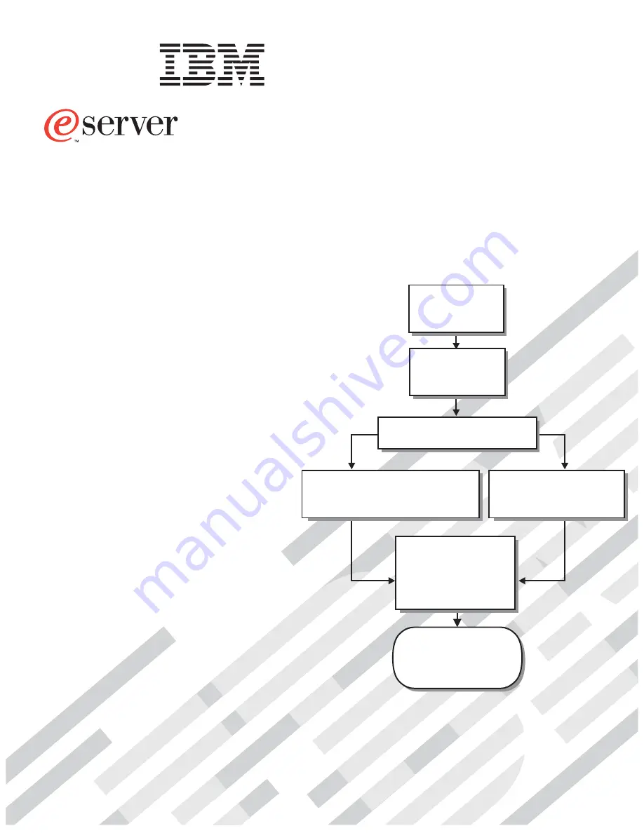
Installation
Guide
and User’s
Documentation CD.
Installation and
User’s Guide
Install and
start the blade
servers
Using ServerGuide
Go to the Web for instructions,
http://www.ibm.com/pc/support
Using the NOS
installation instructions
at www.ibm.com/pc/support
Install additional
applications, such as
IBM systems management
software and IBM
ServeRAID programs on
the blade servers
System is ready to use.
Go to the Server Support
flowchart to register
and profile your server.
Install the
BladeCenter T unit
in the rack.
BladeCenter T
Types 8720 and 8730
Install an operating system on each
blade server (choose one method)
Summary of Contents for BladeCenter T Type 8720
Page 3: ...BladeCenter T Types 8720 and 8730 Installation and User s Guide ERserver...
Page 8: ...vi BladeCenter T Types 8720 and 8730 Installation and User s Guide...
Page 28: ...14 BladeCenter T Types 8720 and 8730 Installation and User s Guide...
Page 64: ...50 BladeCenter T Types 8720 and 8730 Installation and User s Guide...
Page 74: ...60 BladeCenter T Types 8720 and 8730 Installation and User s Guide...
Page 88: ...74 BladeCenter T Types 8720 and 8730 Installation and User s Guide...
Page 122: ...108 BladeCenter T Types 8720 and 8730 Installation and User s Guide...
Page 127: ......
Page 128: ...Part Number 88P9320 Printed in USA 1P P N 88P9320...


