background image

Welcome.

Thank you for buying an
IBM blade server.

For more information about your
BladeCenter components and
features, you can view the
publications on the

http://www.ibm.com/support/

Your blade

server features superior
performance, availability,
and scalability.

This
contains information for setting up,
configuring, and using your
blade server.

Additionally, a service information
label is attached to each BladeCenter
unit and blade server. This label
provides a graphical summary of
many of the installation and service
activities that are associated with
each device.

CD or download from the
IBM Support Web site.

Go to

Installation and User’s Guide

Documentation

Installation and
User’s Guide

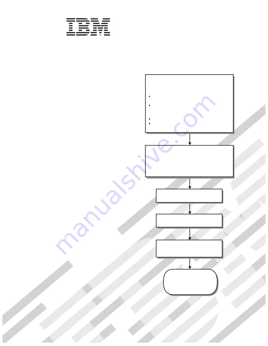
The blade server is now

ready to use. Be sure to

register and profile your

blade server on the

IBM Support Web site.

Before installing the BladeCenter HS20
Type 7981 blade server in a BladeCenter unit,
complete the following procedures:

Install and configure the rack according
to the documentation that came with the rack.
Install the BladeCenter unit into the rack and
configure it, according to the documentation
provided with the BladeCenter unit.
Supply 200-240 V ac to the BladeCenter unit.
Install the latest firmware in all BladeCenter
components.

Before you install the blade server into the
BladeCenter unit, install options such as
drives, memory modules, processor or
expansion cards in the blade server, if applicable.
Install the blade server in the BladeCenter unit.
See Chapter 3 for more information.

BladeCenter HS20

Type 7981

Configure the blade server.
See Chapter 4 for more information.

Install the operating system.
See Chapter 5 for more information.

Install additional applications
according to the instructions provided
with the applications.

Summary of Contents for BladeCenter HS20

Page 1: ...erver on the IBM Support Web site Before installing the BladeCenter HS20 Type 7981 blade server in a BladeCenter unit complete the following procedures Install and configure the rack according to the...

Page 2: ...that all optional devices you installed are on the ServerProven list at http www ibm com servers eserver serverproven compat us Is the server working correctly Is the problem solved Hardware or softwa...

Page 3: ...BladeCenter HS20 Type 7981 Installation and User s Guide...

Page 4: ...ent for your blade server on the Documentation CD and Appendix B Notices on page 65 First Edition March 2006 Copyright International Business Machines Corporation 2006 All rights reserved US Governmen...

Page 5: ...nter unit 22 Opening the blade server cover 23 Installing a SAS hard disk drive 24 Removing a SAS hard disk drive 25 Installing memory modules 25 Removing the blade server bezel assembly 27 Installing...

Page 6: ...Service processor BMC problems 59 Light path diagnostics 59 Diagnosing problems using light path diagnostics 59 Light path diagnostics LEDs 60 Appendix A Getting help and technical assistance 63 Befor...

Page 7: ...alleert eerst de veiligheidsvoorschriften Ennen kuin asennat t m n tuotteen lue turvaohjeet kohdasta Safety Information Avant d installer ce produit lisez les consignes de s curit Vor der Installation...

Page 8: ...ions of the caution or danger statement in the IBM Safety Information book For example if a caution statement begins with a number 1 translations for that caution statement appear in the IBM Safety In...

Page 9: ...quipment when there is evidence of fire water or structural damage v Disconnect the attached power cords telecommunications systems networks and modems before you open the device covers unless instruc...

Page 10: ...VD drives fiber optic devices or transmitters are installed note the following v Do not remove the covers Removing the covers of the laser product could result in exposure to hazardous laser radiation...

Page 11: ...power control button on the device and the power switch on the power supply do not turn off the electrical current supplied to the device The device also might have more than one power cord To remove...

Page 12: ...Statement 13 DANGER Overloading a branch circuit is potentially a fire hazard and a shock hazard under certain conditions To avoid these hazards ensure that your system electrical requirements do not...

Page 13: ...the warranty and getting service and assistance see the Warranty and Support Information document for your blade server on the Documentation CD You can obtain up to date information about the blade s...

Page 14: ...0 Machine type 7981 Model number _____________________________________________ Serial number _____________________________________________ The model number and serial number are on the ID label that i...

Page 15: ...ls comes with the blade server When you install the blade server in the BladeCenter unit write identifying information on a label and place the label on the BladeCenter unit bezel See the documentatio...

Page 16: ...cumentation that comes with the server The documentation might be updated occasionally to include information about those features or technical updates might be available to provide additional informa...

Page 17: ...drive then run the following command from the mnt cdrom directory sh runlinux sh Select your blade server from the Product menu The Available Topics list displays all the documents for your blade serv...

Page 18: ...id inconvenient or problem situations v Attention These notices indicate possible damage to programs devices or data An attention notice is placed just before the instruction or situation in which dam...

Page 19: ...roller v LSI 1064 S Serial Attached SCSI SAS controller v Light path diagnostics v Local service processor BMC v RS 485 interface for communication with the management module v Automatic server restar...

Page 20: ...y The blade server supports up to two Dual Core Intel Xeon processor LV microprocessors Depending on the model the blade server comes with either one or two microprocessors installed In models that co...

Page 21: ...RAS features help to ensure the integrity of the data that is stored in the blade server the availability of the blade server when you need it and the ease with which you can diagnose and correct prob...

Page 22: ...site wss document do lndocid MIGR 61788 It is updated every 6 to 8 weeks v Support for IBM and non IBM servers desktop computers workstations and mobile computers v Support for systems management ind...

Page 23: ...nts The following illustration shows the major components of a BladeCenter HS20 Type 7981 blade server Control Panel Connector Control Panel Cable Heat Sink Microprocessor 2 Microprocessor 1 and Heat...

Page 24: ...12 BladeCenter HS20 Type 7981 Installation and User s Guide...

Page 25: ...r control button During this time the service processor in the management module is initializing therefore the power control button on the blade server does not respond 2 While the blade server is pow...

Page 26: ...v If the operating system stops functioning you can press and hold the power control button for more than 4 seconds to turn off the blade server v The management module can turn off the blade server...

Page 27: ...mal keyboard video mouse switching time frame up to 20 seconds Media Tray select button Press this button to associate the shared BladeCenter unit removable media drives and USB ports with the blade s...

Page 28: ...ol is enabled for the blade server Local power control is enabled and disabled through the management module Web interface System board illustration The following illustration shows the system board c...

Page 29: ...diagnostics LEDs and what to do if there is an error LED lit Table 7 on page 61 provides more information about the light path diagnostics LED locations settings and error solutions Refer to these ill...

Page 30: ...CR4 DIMM 3 error LED CR5 DIMM 4 error LED CR6 There is a problem with the corresponding DIMM SAS hard disk drive LED CR260 and CR262 Reserved BMC fault LED CR11 There is a problem with the BMC Micropr...

Page 31: ...perature of the room where the blade server is installed is within the limits specified by the Features and specifications on page 7 Light path diagnostics LED CR111 Lights to show that the light path...

Page 32: ...20 BladeCenter HS20 Type 7981 Installation and User s Guide...

Page 33: ...any additional procedures that you might have to perform before you remove or install the component v For a list of supported options for the blade server go to http www ibm com servers eserver server...

Page 34: ...er from the BladeCenter unit The following illustration shows how to remove the blade server from Bladecenter type 8677 The appearance of your BladeCenter unit might be different see the documentation...

Page 35: ...pen the blade server cover complete the following steps 1 Read the safety information beginning on page v and Installation guidelines on page 21 2 If the blade server is installed in a BladeCenter uni...

Page 36: ...form factor expansion card occupies the same area as the second hard disk drive To install a SAS hard disk drive complete the following steps 1 Read the safety information beginning on page v and Ins...

Page 37: ...k drive tray away from the hard disk drive to disengage the drive from its tray 6 From the rear edge of the drive slide the drive out of the SAS connector Installing memory modules The following notes...

Page 38: ...blade server it displays a message indicating that the memory configuration has changed Start the Configuration Setup Utility program and select Save Settings See Configuration Setup Utility menu cho...

Page 39: ...ompleting the installation on page 34 Removing the blade server bezel assembly To install certain options you must first remove the blade server bezel assembly The following illustration shows how to...

Page 40: ...che size and type the same clock speed and identical internal and external clock frequencies including system bus speed v Make sure that the microprocessor with the lowest feature set is the startup b...

Page 41: ...socket 90 Lever must be fully open before installing the microprocessor Lever must be fully open before installing the microprocessor ATTENTION b Touch the static protective package that contains the...

Page 42: ...n the socket 9 Install a heat sink on the microprocessor Attention v Do not set down the heat sink after you remove the plastic cover v Do not touch the thermal grease on the bottom of the heat sink T...

Page 43: ...erver with one SAS hard disk drive The blade server supports a number of LAN daughter cards such as v Gigabit Ethernet expansion card v Fibre Channel expansion card v Myrinet expansion card See the Se...

Page 44: ...T A L L IN G C A R D a Orient the expansion card b Slide the notch in the narrow end of the card into the raised hook on the tray then gently pivot the card into the expansion card connectors For dev...

Page 45: ...5 for instructions and save the screws that secure the tray to the system board Store the screws in a safe place 6 Install the expansion card The following illustration shows how to install the expans...

Page 46: ...e server is connected to the power source Always replace the blade cover before installing the blade server 3 Reinstall the blade server into the BladeCenter unit see Installing the blade server in a...

Page 47: ...Important The blade server cannot be inserted into the BladeCenter unit until the cover is installed and closed or an expansion unit is installed Do not attempt to override this protection The followi...

Page 48: ...elines on page 21 through Handling static sensitive devices on page 21 2 If you have not done so already install any options that you want such as SAS drives or memory in the blade server 3 Select the...

Page 49: ...was removed could have unintended consequences and you might have to reconfigure the blade server If this is the initial installation for the blade server in the BladeCenter unit you must configure th...

Page 50: ...utton and the keyboard video mouse select button See Understanding the control panel and LEDs on page 14 for information about these buttons and their functions The Ethernet controllers on the blade s...

Page 51: ...d to select a power management option For information about using this utility program see Using the PXE boot agent utility program on page 45 The IBM Remote Deployment Manager RDM Version 4 20 progra...

Page 52: ...figuration Setup Utility program some of those changes are reflected in the system information you cannot change settings directly in the system information Product Data Select this choice to view the...

Page 53: ...stored after three consecutive failures to find a boot record You can enable a virus detection test that checks for changes in the boot record when the blade server starts This choice is on the full C...

Page 54: ...le and set the time outs for the POST and OS loader watchdog timers and view BMC version information BMC Network Configuration Select this choice to set the network addresses of the BMC BMC System Eve...

Page 55: ...rs and in some cases installing them automatically If a later version of the ServerGuide program is available you can download a free image of the ServerGuide Setup and Installation CD or you can purc...

Page 56: ...ystem installation You can use the ServerGuide program to shorten the installation time The ServerGuide program provides the device drivers that are required for the hardware and for the operating sys...

Page 57: ...start the PXE boot agent utility program complete the following steps 1 Turn on the server 2 When the Broadcom NetXtreme Boot Agent vX X X prompt appears press Ctrl S You have 2 seconds by default to...

Page 58: ...ibm com support The Ethernet controllers in your blade server support failover which provides automatic redundancy for the Ethernet controllers Without failover you can have only one Ethernet control...

Page 59: ...ves are installed Two SAS hard disk drives in the blade server can be used to implement and manage RAID level 0 striping or RAID level 1 mirror arrays in operating systems that are listed on the Serve...

Page 60: ...48 BladeCenter HS20 Type 7981 Installation and User s Guide...

Page 61: ...The BladeCenter unit uses USB for internal communication with these devices 2 Some operating systems such as Red Hat Linux 7 3 enable you to select the type of mouse that is being used If you are off...

Page 62: ...rts RDM see http www ibm com servers eserver xseries systems_management Downloading installation instructions To download operating system installation instructions complete the following steps 1 Go t...

Page 63: ...52 for more information v ServerGuide problems The table in ServerGuide problems on page 54 lists problem symptoms and steps to correct the problems v Troubleshooting charts The Troubleshooting charts...

Page 64: ...red and the BIOS cannot initialize the monitor screen to display additional information Beep codes for specific problems Additional beep codes are listed in the following table Table 4 POST beep code...

Page 65: ...Configuration Setup Utility program and make sure that the parallel port setting is correct 11xx Serial port error Make sure that the serial cable is connected correctly 1162 Serial port configuration...

Page 66: ...ed make sure that the CD ROM drive is first in the startup sequence The operating system installation program continuously loops Make more space available on the hard disk The ServerGuide program will...

Page 67: ...tem management interrupt SMI replace the DIMM v If the DIMMs are not installed in pairs install the DIMMs starting with DIMM 1 and DIMM 2 Make sure that there is not an unpopulated DIMM slot in the mi...

Page 68: ...uring POST followed by a blank monitor screen If this occurs and the Boot Fail Count feature in the Start Options of the Configuration Setup Utility program is enabled its default setting you must res...

Page 69: ...are unable to communicate with the network Make sure that v The I O modules for the network interface that you are using are installed in the correct bays and are configured and operating correctly Se...

Page 70: ...ugh 14 in the BladeCenter unit or blade bays 5 through 8 in the BladeCenter T unit power modules are in all four power bays d The power LED on the blade server control panel is flashing slowly v If th...

Page 71: ...cate the actual component that caused the error locate the lit error LED on that component The following steps illustrate how to use the light path diagnostics to diagnose a system error 1 Shut down t...

Page 72: ...nectors DIMM 4 Error LED CR6 DIMM 3 Error LED CR5 Power is available to relight the light path diagnostics LEDs for a small period of time after the blade server is removed from the BladeCenter unit D...

Page 73: ...lem remains have the blade server serviced Temperature error TEMP The system temperature has exceeded a threshold level v Determine whether a blower on the BladeCenter unit has failed If it has replac...

Page 74: ...62 BladeCenter HS20 Type 7981 Installation and User s Guide...

Page 75: ...device drivers or to submit a request for information You can solve many problems without outside assistance by following the troubleshooting procedures that IBM provides in the online help or in the...

Page 76: ...information about which products are supported by Support Line in your country or region see http www ibm com services sl products For more information about Support Line and other IBM services see ht...

Page 77: ...TY OF ANY KIND EITHER EXPRESS OR IMPLIED INCLUDING BUT NOT LIMITED TO THE IMPLIED WARRANTIES OF NON INFRINGEMENT MERCHANTABILITY OR FITNESS FOR A PARTICULAR PURPOSE Some states do not allow disclaimer...

Page 78: ...demarks and logos are trademarks of Sun Microsystems Inc in the United States other countries or both Adaptec and HostRAID are trademarks of Adaptec Inc in the United States other countries or both Li...

Page 79: ...differ from its retail version if available and may not include user manuals or all program functionality Product recycling and disposal This unit must be recycled or discarded according to applicabl...

Page 80: ...cts of EEE on the environment and human health due to the potential presence of hazardous substances in EEE For proper collection and treatment contact your local IBM representative Battery return pro...

Page 81: ...t cause harmful interference and 2 this device must accept any interference received including interference that may cause undesired operation Industry Canada Class A emission compliance statement Thi...

Page 82: ...equipment Attention This is a Class A product In a domestic environment this product may cause radio interference in which case the user may be required to take adequate measures Taiwanese Class A wa...

Page 83: ...46 cover closing 35 opening 23 D daughter card I O expansion card 32 description DIMM error LED 18 description continued microprocessor error LED 18 SW2 system board switch 17 SW4 system board error...

Page 84: ...nk 30 installing 28 problem 55 specifications 7 microprocessor error LED description 18 N NOS installation with ServerGuide 44 without ServerGuide 45 notes important 66 notices electronic emission 69...

Page 85: ...tatic sensitive devices handling 21 stopping the blade server 14 SW2 system board switch description 17 SW4 location light path diagnostics 17 switch power on password override 43 system board connect...

Page 86: ...74 BladeCenter HS20 Type 7981 Installation and User s Guide...

Page 87: ......

Page 88: ...Part Number 31R1715 Printed in USA 1P P N 31R1715...

Reviews: