


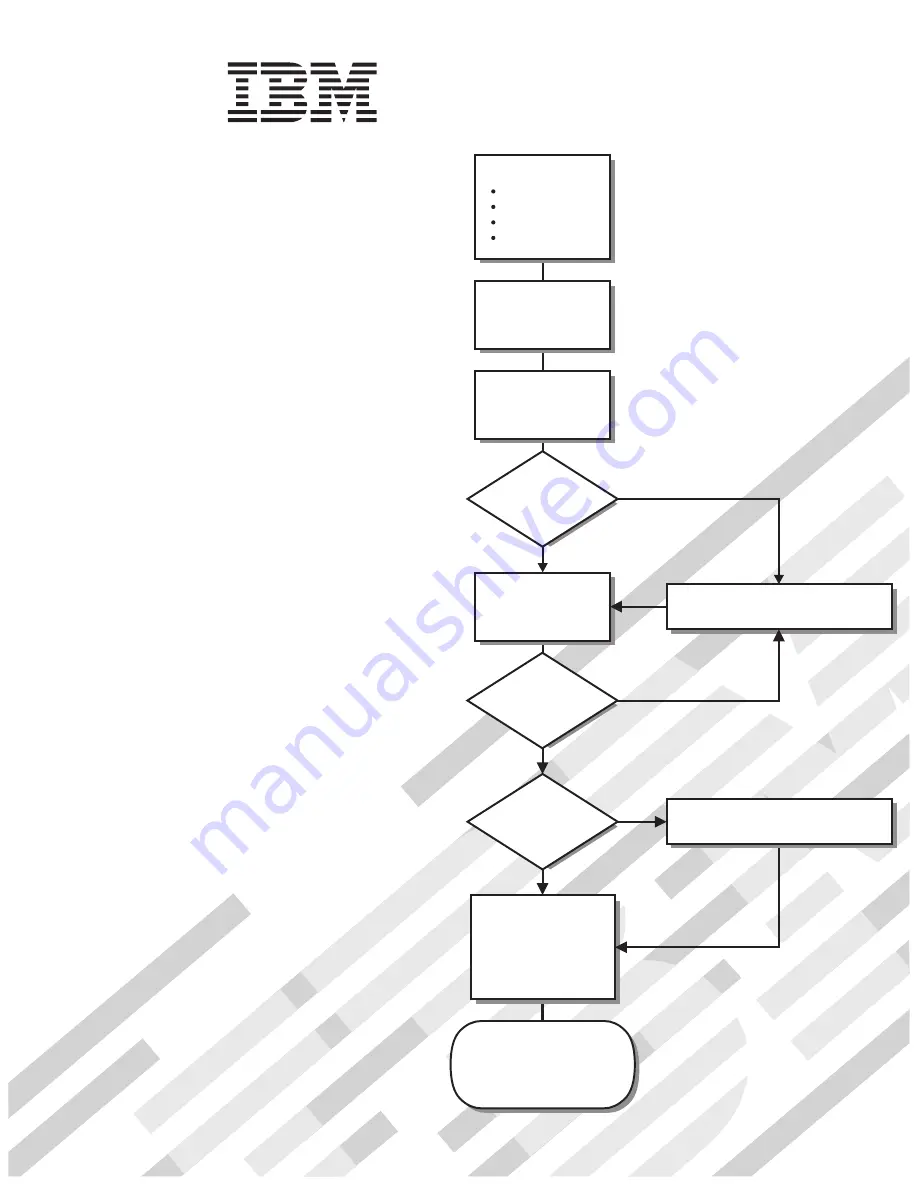
Go to the Server Support
flowchart
Cable the server
and options
Start the server
Install options:
Drives
Microprocessors
Adapters
Memory
Did the server
start correctly?
Yes
No
Use ServerGuide
to set up and
configure hardware
Did configuration
complete?
Use
ServerGuide to
install operating
system?
Install applications,
such as IBM systems
management software
and IBM ServeRAID
programs
System is ready to use.
Go to the Server Support
flowchart to register
and profile your server.
Go to the Web for instructions,
http://www.ibm.com/support
No
Yes
Yes
No
Welcome.
Thank you for buying an
IBM System x server.
This server
contains information for setting
up and configuring your server.
For detailed information about
your server, view the publications
on the
You can also find the most
current information about your
server on the IBM Web site at:
http://www.ibm.com/support
Your server
is based on the X-Architecture
technology, and it features
superior performance, availability,
and scalability.
Documentation CD.
Installation Guide
Installation Guide
Type 8872
and
System x3950
Type 8874
System x3950 E
Summary of Contents for 88728AU - System x3950 - 8872 Datacenter High Availability
Page 3: ...IBM System x3950 Type 8872 and System x3950 E Type 8874 Installation Guide...
Page 42: ...30 IBM System x3950 Type 8872 and System x3950 E Type 8874 Installation Guide...
Page 68: ...56 IBM System x3950 Type 8872 and System x3950 E Type 8874 Installation Guide...
Page 104: ...92 IBM System x3950 Type 8872 and System x3950 E Type 8874 Installation Guide...
Page 105: ......
Page 106: ...Part Number 31R1855 Printed in USA 1P P N 31R1855...


