iBeam TE-PLGCRV, Manual
The iBeam TE-PLGCRV, a cutting-edge electronic device, comes with a comprehensive user manual to assist you in maximizing its potential. Enhance your user experience by downloading the free manual from manualshive.com, enabling seamless understanding and utilization of this remarkable product.
Share
Download


Reviews:
No comments
Related manuals for TE-PLGCRV

22505
Brand: OEM Tools Pages: 4

PRIME DESIGN VRI3-E-PM11
Brand: Safe Fleet Pages: 12

IA-N179
Brand: iArmor Pages: 6

HD 23A 07
Brand: FormFit Pages: 4

STEALTH POWER RBP-216-SP
Brand: RBP Pages: 16
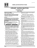
STREET SUPER SHIFTER
Brand: HURST Pages: 2

2013 Nano
Brand: TATA Motors Pages: 136

SR 3 SL
Brand: Radical Sportscars Pages: 44

T4S
Brand: Camoplast Pages: 19

KT-76
Brand: ENSONIQ Pages: 249

2012 Sienna
Brand: Toyota Pages: 779

nERGY ETSA200R-PA
Brand: Soundoff Signal Pages: 3

Mover H SE
Brand: Truma Pages: 10

Ridesmart KMA-610
Brand: KlipXtreme Pages: 12

Laguna III
Brand: Renault Pages: 3699

2015 Forester
Brand: Subaru Pages: 16

38508
Brand: Brainz Pages: 2

50085
Brand: Reese Pages: 21


