IBA PROFIBUS ibaBM-DP, Manual
The IBA PROFIBUS ibaBM-DP manual is essential for understanding the functions and features of this product. You can download the manual for free from our website to ensure easy installation and operation. Get the most out of your device with the comprehensive user manual.
Share
Download


Reviews:
No comments
Related manuals for PROFIBUS ibaBM-DP
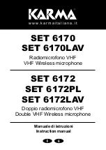
6170
Brand: Karma Pages: 12

Radius 100M
Brand: Alto Pages: 60

E 825 S - 07-06
Brand: Sennheiser Pages: 9

DAISY VR6
Brand: Zack Audio Pages: 32

Mic Studio 100 Pro
Brand: WOXTER Pages: 8

studio 1
Brand: MXL Pages: 6

WX-LZ110
Brand: Panasonic Pages: 2

WX-SR202P
Brand: Panasonic Pages: 116

AWM6502U
Brand: Audio2000's Pages: 6

PRO 88W
Brand: Audio Technica Pages: 8

ATW-600
Brand: Audio Technica Pages: 2

77-DX MI-4045-F
Brand: RCA Pages: 8

PC Sat-12
Brand: Electro-Voice Pages: 4

RFM5104
Brand: RFMicron Pages: 24

MC04
Brand: SM Pro Audio Pages: 12

QUICKTIP
Brand: Starkey Pages: 3

uber mic
Brand: M-Audio Pages: 44

3300128
Brand: Radio Shack Pages: 7


