Hypertherm POWERMAX 800, Service Manual
The Hypertherm POWERMAX 800 is a powerful cutting tool that delivers exceptional performance. To ensure optimal usage, make sure to download the Operator's Manual from our website for free. This comprehensive manual provides step-by-step instructions, safety guidelines, and troubleshooting tips to maximize your experience with this incredible product.
Share
Download


Reviews:
No comments
Related manuals for POWERMAX 800

181LETCUT1
Brand: Garde Pages: 4

Klauke Mini ES 32FML
Brand: Emerson Pages: 13

Klauke EK 60VPFTCFB
Brand: Emerson Pages: 13

Klauke EBS8CFB
Brand: Emerson Pages: 14
Klauke BTC3
Brand: Emerson Pages: 15

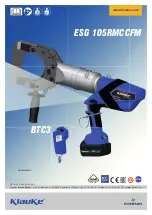
Klauke ESG 105CFM
Brand: Emerson Pages: 10

Klauke ESG 25CFM
Brand: Emerson Pages: 20

KlauKe ES 32RMCCFM
Brand: Emerson Pages: 21

Torch Runner
Brand: SteelMax Pages: 42

PETITE MERVEILLE BRC-26 HYDRO
Brand: Schiller Pages: 78

IC1AL
Brand: REED Pages: 2

CTRTC800-200
Brand: Constructor Pages: 43

RCR2660
Brand: Land Pride Pages: 40

RD-ETC25
Brand: Raider Pages: 60

ESSENTIAL OXYCUTTING
Brand: Lincoln Electric Pages: 42

BCL330
Brand: Masport Pages: 7

Vitrex Versatile Power Max 560
Brand: QEP Pages: 5

10221Q
Brand: QEP Pages: 8


