Hypertherm powermax 190c, Service Manual
The Hypertherm Powermax 190c is a high-performance cutting machine. To ensure proper maintenance and troubleshooting, download the free service manual from manualshive.com. This comprehensive manual provides detailed instructions and diagrams, allowing users to optimize their experience with this top-notch product. Get your manual today and unleash the power of the Powermax 190c.
Share
Download


Reviews:
No comments
Related manuals for powermax 190c

92 21 48
Brand: Westfalia Pages: 90

YM415FW
Brand: Zenoah Pages: 8

FX-RT226
Brand: FUXTEC Pages: 52

HDC 350
Brand: Belle Group Pages: 32

Klauke SDK 502
Brand: Textron Pages: 12

Mat Master 1060B System
Brand: FrameCo Pages: 12

AMH-200-4S-ELITE
Brand: Agrimate Pages: 22

77HRB
Brand: Current Tools Pages: 6

707
Brand: Logan Graphic Products Pages: 4

Performance series
Brand: Datamax Pages: 15

RC5020 Series
Brand: Land Pride Pages: 70

SmartCut A525pro
Brand: Rexel Pages: 1

35-L
Brand: IBEA Pages: 80
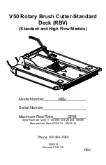
RBV V50
Brand: Talet Equipment Pages: 20

ZI-FTS115
Brand: Zipper Mowers Pages: 28

Evolution Bench
Brand: KEENCUT Pages: 10

Power Edger
Brand: Echo Pages: 32

GWS Professional 850 C
Brand: Bosch Pages: 137


