HYDAC FILTER SYSTEMS OLFP-3 Series, Installation And Maintenance Instructions Manual
The HYDAC FILTER SYSTEMS OLFP-3 Series offers top-notch filtration capabilities. To understand the required installation and maintenance procedures, you can conveniently download the comprehensive "Installation And Maintenance Instructions Manual" for free at manualshive.com. This manual will serve as your user-friendly guide, ensuring optimal product performance.
Share
Download


Reviews:
No comments
Related manuals for OLFP-3 Series

50808
Brand: NatureWater Pages: 16

UF Series
Brand: RainSoft Pages: 16

Aqua-Pure 3MFF100
Brand: 3M Pages: 8

50877
Brand: NatureWater Pages: 5

R14-02
Brand: Alamo Water Pages: 44

ProfiClear Premium XL Moving Bed Modul
Brand: Oase Pages: 105
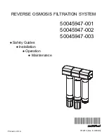
50045947
Brand: Honeywell Pages: 24
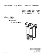
50045947-001/011
Brand: Honeywell Pages: 20

CUF Series
Brand: SunSun Pages: 9

HYDROSMART VENEZIA
Brand: Laica Pages: 76

EC1
Brand: IDEAL Pages: 68

S1
Brand: Allfyll Pages: 16

WDP
Brand: Munters Pages: 48

AIF10
Brand: Water Channel Partners Pages: 23

LT ecocool 100
Brand: Grant Pages: 5

Kwik-Change
Brand: Watts Pages: 4

2700 SERIES
Brand: AVK Pages: 27

SQC Pro
Brand: Cuno Pages: 15


