HYDAC FILTER SYSTEMS OF5 N Series, Installation And Maintenance Instructions Manual
The HYDAC FILTER SYSTEMS OF5 N Series is a high-performance filtration solution designed to efficiently clean fluids. Ensure accurate installation and routine maintenance by downloading our comprehensive "Installation And Maintenance Instructions Manual" for free. Unlock the full potential of your filter system now at manualshive.com, where hassle-free manual downloads are just a click away.
Share
Download


Reviews:
No comments
Related manuals for OF5 N Series

Osmo
Brand: W&H Pages: 36

AIRONE FC 750
Brand: Safelab Pages: 20

GreenKeeper 212
Brand: Toro Pages: 39

BASIKA rho NS 10
Brand: Magus Pages: 30

DW 2800
Brand: waterlovers Pages: 12

Bitron 9C
Brand: Oase Pages: 102

ESFR
Brand: Viking Pages: 53

028084
Brand: Dantherm Pages: 8

10031071
Brand: Waldbeck Pages: 13

M5PT
Brand: Waterdrop Pages: 2

MF90-12BI
Brand: Dean Pages: 33
NL4-LBM Series
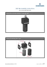
Brand: Emerson Pages: 3
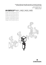
AVENTICS AS1
Brand: Emerson Pages: 47

CQE-SP-00809
Brand: Crystal Quest Pages: 2

ULTRAPROBE 201
Brand: UE Systems Pages: 13

TP955.V2
Brand: Sealey Pages: 5

Resilience CLGE40
Brand: Solaxx Pages: 15

Total Access Total Access 19-Inch Fan Filter
Brand: ADTRAN Pages: 2


