background image


3


GENERAL DESCRIPTION 

PACKING LIST 

The Hy-Gain MK-80 add on kit contains 

• 

5 hose clamps all 

of the necessary parts and instructions 
to make a Hy-Gain 14AVQ vertical 

• 

10 36" spokes (2 extra)  resonate on 80 

meters. The 80-meter kit 

• 

Loading coil assembly features stainless steel hardware 

and 
hose clamps. The loading coil is wound 

• 

18 4-40 screws (2 extra) 

onto a 1 inch fiberglass tube using #14 

• 

18 4-40 kep nuts (2 extra) 

Teflon insulated wire for extended life. 
The antenna is capable of 1 KW PEP on 

, 1 1/8" X 17" aluminum tube 80-

meters. 

secure the MK-80 to an existing AV 

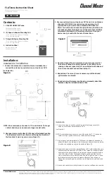
1. Remove the parts from the 

14AVQ antenna. See Figure 1. 

packaging. Check to see that each is 
present using the packing list above. 

6. Place four capacitance spokes into 

each of the spoke rings located on the 

2. Place a 4-40 screw in each of the 16  loading coil assembly and secure  holes on the 

capacitance spoke rings them in place by tightening the 4-40 and secure them using a 
4-40-kep 

screws. 

nut. Refer to figure 1. Snug each one  

using a 5/16" nut driver. Be careful 
not to lose the screws and nuts. 

3. Place  the large end of the 1 1/8" X 

17" aluminum tubing over the end of 
the loading coil assembly tube as 
shown in Figure 1. 

4. Secure the tubing in place with one of 

the supplied hose clamps. Be sure to 
place the connection tab between the 
aluminum tubing and the clamp as 
shown in Figure 1. 

5. Place the remaining hose clamp onto the 

aluminum tube. This clamp is used to 


Summary of Contents for MK-80

Page 1: ...re 1 packaging Check to see that each is present using the packing list above 6 Place four capacitance spokes into each of the spoke rings located on the 2 Place a 4 40 screw in each of the 16 loading coil assembly and secure holes on the capacitance spoke rings them in place by tightening the 4 40 and secure them using a 4 40 kep screws nut Refer to figure 1 Snug each one using a 5 16 nut driver ...

Page 2: ...th the MK 80 directly above the black ABS cover of trap 15 20 Figure 1 on page 4 shows the location of this trap d Do not place tubing section M5 onto the antenna If this section is 3 Place the assembled MK 80 onto the assembled AV 14AVQ antenna The 1 1 8 x 17 tubing has been fitted to accept the AV 14AVQ 4 Secure the tubing in place by tightening the hose clamp placed on the MK 80 in step 5 of th...

Page 3: ... on the 80 Meter band with the spokes installed The SWR should be at a minimum near 3 5 MHz 2 To raise the operating frequency cut small lengths such as 4 inch lengths from each of the four 80 Meter spokes Check the resonance point again Continue the previous steps until the desired frequency is reached SERVICE INFORMATION If you have a problem you are unable to resolve or if you need to order rep...

Page 4: ...ctive product under warranty provided the product is returned postage prepaid to hy gain with a personal check cashiers check or money order for 8 00 covering postage and handling 3 Under no circumstances ishy gain liable for consequential damages to person or property by the use of anyhy gain products 4 Out of warranty Service hy gain will repair any out of warranty product providedthe unit is sh...

Reviews: