Husqvarna YTH24V54XLS, Owner'S Manual
The Husqvarna YTH24V54XLS is a top-quality lawn tractor that offers exceptional performance and durability. To harness the full potential of this fantastic machine and ensure its longevity, it is crucial to refer to the comprehensive Owner's Manual. Download the manual for free from manualshive.com and unlock the full potential of your Husqvarna YTH24V54XLS.
Share
Download


Reviews:
No comments
Related manuals for YTH24V54XLS

567
Brand: Yard-Man Pages: 32

TSW-210
Brand: Tanaka Pages: 8

MX 5000
Brand: Toro Pages: 2
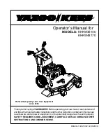
KHKW36140
Brand: Yazoo/Kees Pages: 19

ZYJ-1361-A
Brand: Yard-Man Pages: 6

RAC1200EM-UK
Brand: Racing Pages: 20

11A-B0BL765
Brand: Troy-Bilt Pages: 40

NXT 7800752
Brand: Snapper Pages: 72

247.289841
Brand: Craftsman Pages: 100

247.288851
Brand: Craftsman Pages: 92

247.37000
Brand: Craftsman Pages: 56

247.288820
Brand: Craftsman Pages: 96

247.28880
Brand: Craftsman Pages: 100

247.25001
Brand: Craftsman Pages: 112

247.25002
Brand: Craftsman Pages: 112

247.250610
Brand: Craftsman Pages: 120

247.288811
Brand: Craftsman Pages: 92

247.289150
Brand: Craftsman Pages: 184


