Husqvarna TE 250i 2022, User Manual
The Husqvarna TE 250i 2022 is a top-notch off-road motorcycle that ensures a thrilling riding experience. Designed with cutting-edge technology, it offers superior performance and precision. To get the most out of your TE 250i, make sure to download the free user manual from manualshive.com for comprehensive instructions and valuable insights.
Share
Download


Reviews:
No comments
Related manuals for TE 250i 2022

MX400
Brand: Cannondale Pages: 61

SR Series
Brand: ZERO GRAVITY Pages: 6

TBR7
Brand: Tao Motor Pages: 3

Star XV250ZC
Brand: Yamaha Pages: 96

ECC0300R
Brand: R&G Pages: 6

CRUISER400
Brand: Braaap Pages: 40

EC-SIX DAYS - PART LIST 2011
Brand: GAS GAS Pages: 6
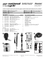
Quantum hardcoated N30214-WK
Brand: National Cycle Pages: 13

6317588 00 01L
Brand: hepco & becker Pages: 3

2X2 SE 2023
Brand: UBCO Pages: 27

SHERCO 50 SE 2022
Brand: SHERCO Pages: 226

633844 IT
Brand: VESPA Pages: 308

2Q000504
Brand: APRILIA Pages: 597

VarioProtect XXL-W-2 TC
Brand: Schweißkraft Pages: 16

Marathon 450
Brand: RIEJU Pages: 148

MRT 50
Brand: RIEJU Pages: 162

iLogger easy
Brand: Healtech Pages: 5

CRF125F 2021
Brand: Honda Pages: 132


