background image

HUSKIE 
HYDRAULIC 
HAMMERS


SERVICE  
MANUAL


HH100 


HH150-2


HH300-2 


HH500-2 


HH750-2


HH1000-2


Summary of Contents for HH100

Page 1: ...HUSKIE HYDRAULIC HAMMERS SERVICE MANUAL HH100 HH150 2 HH300 2 HH500 2 HH750 2 HH1000 2 ...

Page 2: ...2 ...

Page 3: ...nderwater Operation Storage Tool Replacement 3 Maintenance Page 13 Hydraulic Oil Checking Condition of Hydraulic Oil Fasteners Greasing Requirements Nitrogen N2 Gas Pressure Adjustment Oil Leakage Inspection Gas Leakage Inspection 4 Disassembly and Assembly Page 19 Disassembly Inspection of Parts Component Wear Limits Assembly 5 Specifications Page 26 6 Refinishing of Pistons and Cylinders Page 27...

Page 4: ... s seat ONLY Make sure the seat is fastened securely before activating controls Keep hands and feet on the controls at all times while the hammer is operating Always operate the carrier with the outriggers firmly positioned on the surface Make sure all controls levers and pedals are in NEUTRAL before starting the carrier NEVER leave the carrier with the engine running ALWAYS ENGAGE THE PARKING BRA...

Page 5: ...d or illegible Decals can be ordered through parts department DANGER This symbol may appear on the hammer or in the text of this manual It is used to alert the operator of an action that can place him her or others in a life threatening situation CAUTION This symbol appears in the text of this manual to identify an action or condition that can result in damage to the hammer or other equipment ...

Page 6: ...tool rock or other broken material may cause serious or fatal injury to bystanders Do not operate the hammer when bystanders are in the area In some cases the hammer may enter the operator s area if a bracket or cylinder breaks Make sure appropriate shields are used when operating the hammer with this type of equipment Shown above is a copy of a decal that must be installed on a surface of the ham...

Page 7: ...lve directs flow to the upper chamber causing it to become high pressure Since surface A is greater than surface B the piston is driven downward with the help of the accumulated energy from the gas chamber creating the impact stroke of the hammer At the point of impact the main valve shifts releasing the high pressure from the upper chamber enabling the upward stroke to occur again Figure 1 Princi...

Page 8: ...NG HOSES Connect the two hydraulic hoses to the inlet and outlet ports of the carrier using hose couplers When connecting make sure that the couplers are clean and engaged securely DAILY INSPECTION BEFORE OPERATION 1 Check the carrier hydraulic oil level before operation The hydraulic oil level must be correct for proper operation 2 Check the hydraulic oil for any signs of contamination or discolo...

Page 9: ... inward 6 Do not submerge the hammer in water The hammer is not watertight and damage can occur if used in this manner Consult your dealer for underwater applications Ref Figure 3 7 Do not use the hammer to move very large or heavy broken objects This can cause damage to the hammer and carrier 8 Do not use the hammer as a lifting device 9 Do not operate the hammer when boom cylinders are at their ...

Page 10: ...an external compressed air supply a For HH100 through HH500 2 5 10 CFM at 50 to 90 psi is adequate b For HH750 2 and HH1000 2 20 to 50 CFM is required 2 Connect air supply line to front cap threaded port remove plug P N 3Z01 FP0038 as shown Thread is 3 8 inch pipe tapered 3 Set pressure regulator to 50 90 psi 4 Maintain air supply to hammer at all times when operating under water PRESSURE REGULATO...

Page 11: ...ove and clean the tool Flush the front cap with clean solvent or hydraulic oil Coat the exposed portion of the piston with grease apply grease to the tool and re install Store the hammer vertically and away from standing moisture To start the hammer after long term storage remove the tool and inspect the exposed portion of the piston for corrosion If corrosion is found do not use the hammer until ...

Page 12: ...50 2 manual removal is possible For the hammer models HH1000 2 and larger use hoist and sling as shown Check for sling load rating and compare to Table 1 Page 11 When installing the tool in the hammer reverse steps 1 through 4 above Note that tool spring pin must be inserted with the slot or open side away from the tool set pin Figure 4 Tool Replacement 4 60 o 1 3 1 3 1 3 SLING ANGLES NOT SMALLER ...

Page 13: ...should not exceed 180 F 80 C 4 Check the condition of the hydraulic oil as specified in Table 2 CHECKING CONDITION OF HYDRAULIC OIL Note Refer to carrier service manual for proper class and type of hydraulic oil Hydraulic oil must be changed more frequently than the carrier instruction manual recommends This is because hammer operation requires more oil circulation than normal operation Oil condit...

Page 14: ... across flats Table 3 Bolt Sizes GAS VALVE HAMMER NIPPLES mm BRACKET BOLTS mm SIDE ROD BACK NUT mm SIDE ROD ALLEN HEAD mm LIFTING EYES inches CAP inches BODY mm HH100 19 28 NA 14 13pt 1 Crow Foot 36 HH150 2 30 36 32 NA 13pt 1 Crow Foot 36 HH300 2 30 36 41 NA 13pt 1 Crow Foot 36 HH500 2 30 36 41 14 10pt 1 Crow Foot 36 HH750 2 30 36 46 14 10pt 1 Crow Foot 36 HH1000 2 36 50 46 17 10pt 1 Crow Foot 36 ...

Page 15: ...A NA NA NA NA Bracket Bolt 150 35 260 35 260 35 260 35 260 35 400 35 GREASING REQUIREMENTS The hammer should be greased each startup and after every 2 3 hours of operation The grease nipple is located at the front cap as shown in Figure 6 Approximately 10 shots in the front cap are recommended when the tool is at the upper limit of travel Figure 6 Grease Fitting Figure 6 1 3 4 2 5 1 3 6 2 4 7 1 3 ...

Page 16: ... hose connection port of the gas charger with the cap provided then turn the T handle fully to the left counter clockwise b Remove the gas valve cap located on the hammer back cap and attach gas charger see Figure 7 Figure 7 Connecting Gas Charger to Hammer Figure 8 Connecting Gas Charger to Nitrogen N2 Supply c Turn the T handle on the gas charger valve clockwise and then measure the N2 gas press...

Page 17: ...as Charger Valve d Open the main gas valve on the N2 gas container and regulate the N2 gas pressure see Figure 8 e Turn the gas charger T handle clockwise and adjust N2 gas pressure in the gas chamber to the correct gas pressure shown on Table 10 Page 26 f Turn the gas charger T handle fully counter clockwise and remove the hose Attach the cap to the gas inlet of the charger g Remove the gas charg...

Page 18: ... LEAK LOCATION POSSIBLE CAUSE REMEDY Between front cap and tool E Damaged or worn U packing Replace seal kit Between cylinder and nipple F Loose nipple or damaged O ring or nipple Tighten or replace nipple and or O ring Between cylinder and back cap G Damaged U packing or main Valve outer sleeve O ring or Back cap O ring Replace seal kit Plug ports H Plugs loosen Remove plugs and reinstall with se...

Page 19: ... Diagnosis of Gas Leakage LEAK LOCATION POSSIBLE CAUSE REMEDY Gas valve assembly A or Between gas valve assembly and back cap B Defective O ring damaged Spring or gas valve Replace gas valve assembly Between back cap and cylinder C Defective back cap O ring Replace back cap O ring Figure 11 4 DISASSEMBLY AND ASSEMBLY ...

Page 20: ...Install an eyebolt and suspend the front cap as shown in Figure 12 Pull out the front cap being careful not to damage the piston Figure 12 Connecting Hoist to Front Cap 4 Main valve Attach an eyebolt to outer sleeve and remove it by pulling the eyebolt Figure 13 Remove the main valve The inner sleeve cannot be removed it is press fitted and requires a special tool Contact the factory for further d...

Page 21: ...eve Remove the cylinder sleeve from the piston A plastic hammer or nylon bar can be used for removal as shown in Figure 15 Do not force the cylinder sleeve Tap uniformly on all sides of the sleeve Figure 15 Removing Cylinder Sleeve Note Support piston on wood blocks Table 7 Piston Weights WEIGHTS HAMMER MODEL kg lbs HH100 5 8 12 7 HH150 2 6 0 13 2 HH300 2 9 7 21 3 HH500 2 10 0 22 0 HH750 2 17 1 37...

Page 22: ...oval e Install the new front cap bushing in the correct direction with part numbers on the bushing facing the installer away from the hammer Because the bushings are a press or interference fit heating of the front cap and cooling of the bushing will help installation f Insert the bushing set pin and the bushing spring pin 5 Replacing the shank bushing Note Replacement of the front cap bushing is ...

Page 23: ...t is not necessary to completely remove scratches only the sharp edges as this may remove excess material Figures 19 20 and 21 Page 27 c Main Valve and Sleeves Main valve and sleeves cannot be polished Replace if these parts do not slide freely by finger pressure COMPONENT WEAR LIMITS Parts are to be replaced if they are not within the wear parameters See Table 8 and Figure 17 for new dimensions s...

Page 24: ... 2 HH300 2 HH500 2 HH750 2 HH1000 2 Front Cap Bushing I D 41 mm 1 614 in 51 mm 2 008 in 61 mm 2 402 in 66 mm 2 598 in 76 mm 3 0 in 91 mm 3 583 in Shank Bushing I D 41 mm 1 614 in 51 mm 2 008 in 61 mm 2 402 in 66 mm 2 598 in 76 mm 3 0 in 91 mm 3 583 in Tool O D 40 mm 1 575 in 50 mm 1 768 in 60 mm 2 362 in 65 mm 2 559 in 75 mm 2 953 in 90 mm 3 543 in HH100 does not have replaceable bushings Measurem...

Page 25: ...cylinder 5 Insert the main valve and the outer sleeve 6 Apply hydraulic oil into the back cap for gas seal lubrication See Figure 18 7 Attach the back cap to the cylinder Figure 18 Adding oil to the Back Cap 8 Insert and tighten the four side rods together with the washer to the specified torque see Table 4 and Figure 5 on page 15 9 Refill the hammer with Nitrogen N2 gas Refer to pages 16 and 17 M...

Page 26: ...t the hose end of the carrier pressure hose when disconnected from the hammer The nitrogen charge in a hammer is directly related to the operating pressure of the circuit powering it An increase of 10 in gas charge will cause a 10 rise in hammer operating pressure This is prevalent in hammers if gas pressure has been set or checked on a cool morning 600 F and then run in increasingly higher ambien...

Page 27: ...p type wheels Two grit wheels were used 240 for Heavy Polish 360 for Finishing Figure 19 Rotate piston and polish with brushing motion of grinder Polish total area before changing to fine grit for finishing Figure 20 After completion of fine polishing clean labyrinth grooves carefully with fine needle file to remove all burrs and rough edges Figure 21 After polishing all rough surfaces and edges c...

Page 28: ...p Repair pump Oil temperature is too high exceeds 180 F or 80 C Check oil cooler Main valve is damaged Replace damaged main valve Decreased oil flow Avoid simultaneous axis movement Auto shut off in operation tool is suspended Apply proper down force Excessive bushing wear Replace worn bushings Hesitation or erratic operation Piston is damaged Repair or replace piston Nitrogen pressure is too high...

Page 29: ...t cap bushing Includes removal and re installation hammer disassembly not required HH150 HH1000 hour Shank bushing Includes complete disassembly removal of both bushing and re assembly HH150 HH1000 3 hours Side rod replacement only Includes complete disassembly removal of broken side rod and re assembly HH150 HH1000 2 hours Bracket bolt replacement HH100 HH1000 hour ...

Page 30: ...misuse lack of maintenance accident or use of the Product beyond its published design capacity specifications or recommended applications The Manufacturer will authorize the return of defective components to the Manufacturers warehouse or location specified by the Manufacturer The Manufacturer will determine if said components show clear and evident proof of defective material and or workmanship A...

Page 31: ... and Using the Warranty Claim Form Fill out all items as completely as possible Take note of 5 below In the section titled DESCRIPTION OF FAILURE describe the failure as clearly as possible along with operating conditions of the hammer and carrier as best you can In order for IPC to consider DEALER LABOR and DEALER MILEAGE in your claim your published labor and mileage rates must be on file with I...

Page 32: ...If a part is particularly heavy please contact us for further information 8 Warranty Part Freight Costs IPC Industries Inc will cover inbound when requested by IPC and outbound freight for warranted parts under the following circumstances only IPC will cover surface freight costs for parts judged to be defective in materials or workmanship The cost of shipping warranted parts via an expedited surf...

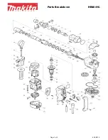
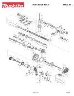
Page 33: ...33 9 PARTS LIST AND ILLUSTRATIONS HH100 HH150 2 HH300 2 HH500 2 HH750 2 HH1000 2 ...

Page 34: ...81 1 14 Plug O Ring 3A01 09040W 1 15 Back Cap 3A01 2010031 1 16 O Ring 3A01 07148A 1 17 Gas Valve Assembly 3Z01 G00001 1 18 Gas Valve Cap with O Ring 3Z01 G00004 1 19 Front Cap 3A01 2010041 1 20 Grease Nipple 3A01 AMT6075 1 21 Tool Set Pin 3A01 2010061 1 22 Tool Spring Pin 3A01 S24080 1 23 Back Cap Set Bolt A 3A01 B40258 2 24 Back Cap Set Bolt B 3A01 B40148 2 25 Front Cap Set Bolt 3A01 B40148 4 26...

Page 35: ...35 HH100 HAMMER Effective 07 09 ...

Page 36: ... 1 Hammer Bracket R 2 1 Hammer Bracket L 3 3A01 311050ME 3 Bracket Bolt 4 3A01 311060ME 1 Bracket Bolt 5 Assembly of Item 3 and 4 4 Nut 6 3A01 311091ME 1 Support Pipe 7 By Carrier Model 4 Bushing 8 By Carrier Model 2 Pin Sold as matched set w hardware Effective 07 09 HH100 MINI EXCAVATOR ...

Page 37: ...37 ...

Page 38: ...3C01 07148A 1 18 Front Cap 3C01 2020041 1 19 Front Cap Plug 3Z01 FP0038 1 20 Shank Bushing 3C01 010042 1 21 Front Cap Bushing 3C01 010043 1 22 Bushing Set Pin 3C01 010044 2 23 Bushing Spring Pin 3C01 S34058 4 24 Nipple PF 1 2in 3 4in UN 3C03 N00001 2 25 O Ring Not sold separately included w 24 3C03 07058B 2 26 Side Rod Assembly 3C01 010051 4 27 Side Rod Washer Included w 26 3C01 010054 4 28 Grease...

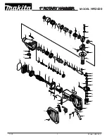
Page 39: ...39 HH150 2 HAMMER S N 001 099 2B2 1000 UP Effective 07 09 ...

Page 40: ...1 3C02 311021MF 1 Hammer Bracket R 2 1 Hammer Bracket L 3 3C01 311050SS 2 Bracket Bolt 4 3E01 206602SM 1 Bracket Bolt 5 Assembly of Item 3 4 3 Nut 6 By Carrier Model 4 Bushing 7 By Carrier Model 2 Pin Sold as matched set w hardware Effective 07 09 HH150 2 SKID STEER MULTI FIT ...

Page 41: ...41 ...

Page 42: ...3D01 07178A 1 18 Front Cap 3D01 2030041 1 19 Front Cap Plug 3Z01 FP0038 1 20 Shank Bushing 3D01 030042 1 21 Front Cap Bushing 3D01 030043 1 22 Bushing Set Pin 3D01 060344 2 23 Bushing Spring Pin 3C01 S34058 4 24 Nipple PF 1 2in 3 4in UN 3C03 N00001 2 25 O Ring Not sold separately included w 24 3C03 07058B 2 26 Side Rod Assembly 3D01 030051 4 27 Side Rod Washer Included w 26 3D01 030054 4 28 Grease...

Page 43: ...43 HH300 2 HAMMER S N 001 099 2E2 1000 UP Effective 07 09 ...

Page 44: ...T PART NO ITEM MODEL HH300 2 QTY DESCRIPTION 1 3D02 312021MF 1 Hammer Bracket R 2 1 Hammer Bracket L 3 3D01 312051MF 4 Bracket Bolt 4 Assembly of Item 3 4 Nut 5 By Carrier Model 4 Bushing 6 By Carrier Model 2 Pin Sold as matched set w hardware Effective 07 09 ...

Page 45: ... Hammer Bracket R 2 1 Hammer Bracket L 3 3D01 312051MF 4 Bracket Bolt w nut 4 Assembly of Item 3 4 Nut 5 By Carrier Model 2 Variable Plate 6 By Carrier Model 4 Bushing 7 By Carrier Model 2 Pin 8 3Z01 5161834 4 Set Screw Sold as matched set w hardware Effective 07 09 HH300 2 MULTI FIT VARIABLE ...

Page 46: ...nut 3 Assembly of Item 3 4 Nut 4 3D01 TC300B 6 Top Cap Bolt w nut washer 5 3D01 TC300W 6 Top Cap Washer 6 3D01 TC300N 6 Top Cap Nut 7 3Z01 5161834 4 Set Screw 8 Per Carrier Model 1 Top Cap 9 By Carrier Model 4 Bushing 10 By Carrier Model 2 Pin 11 By Carrier Model 2 Variable Plate HH300 2 FLANGE MOUNT Sold as matched set w hardware Effective 07 09 ...

Page 47: ......

Page 48: ...includes item 19 3Z01 G00001 1 19 Gas Valve Cap with O Ring 3Z01 G00004 1 20 Front Cap 3G02 H060041 1 21 Front Cap Plug 3Z01 FP0038 1 22 Shank Bushing 3G02 H060042 1 23 Front Cap Bushing 3G01 050043 1 24 Bushing Set Pin 3D01 060344 2 25 Bushing Spring Pin 3C01 S34058 4 26 Nipple PF 1 2in 3 4in UN 3C03 N00001 2 27 O Ring Not sold separately included w 26 3C03 07058B 2 28 Side Rod Assembly 3G02 H060...

Page 49: ...49 HH500 2 HAMMER S N 001 099 2R2 1000 UP Effective 07 09 ...

Page 50: ...QTY DESCRIPTION 1 3D02 312021MF 1 Hammer Bracket R 2 1 Hammer Bracket L 3 3D01 312051MF 4 Bracket Bolt 4 Assembly of Item 3 4 Nut 5 By Carrier Model 4 Bushing 6 By Carrier Model 2 Pin Sold as matched set w hardware Effective 07 09 HH500 2 SKID STEER MULTI FIT ...

Page 51: ...Hammer Bracket R 2 1 Hammer Bracket L 3 3D01 312051MF 4 Bracket Bolt w nut 4 Assembly of Item 3 4 Nut 5 By Carrier Model 2 Variable Plate 6 By Carrier Model 4 Bushing 7 By Carrier Model 2 Pin 8 3Z01 5161834 4 Set Screw Sold as matched set w hardware Effective 07 09 HH500 2 VARIABLE MULTI FIT ...

Page 52: ...t 3 Assembly of Item 3 4 Nut 4 3D01 TC300B 6 Top Cap Bolt w nut washer 5 3D01 TC300W 6 Top Cap Washer 6 3D01 TC300N 6 Top Cap Nut 7 3Z01 5161834 4 Set Screw 8 Per Carrier Model 1 Top Cap 9 By Carrier Model 4 Bushing 10 By Carrier Model 2 Pin 11 By Carrier Model 2 Variable Plate Sold as matched set w hardware Effective 07 09 HH500 2 FLANGE MOUNT ...

Page 53: ...1 Hammer Bracket R 2 1 Hammer Bracket L 3 3D01 312051MF 4 Bracket Bolt 4 3E01 31208TLB 1 Bracket Bolt 5 Assembly of Item 3 and 4 5 Nut 6 3E01 31209TLB 1 Support Pipe 7 By Carrier Model 4 Bushing 8 By Carrier Model 2 Pin Sold as matched set w hardware Effective 07 09 HH500 2 SLIP FIT TLB WLB ...

Page 54: ...ludes item 19 3Z01 G00001 1 19 Gas Valve Cap with O Ring 3Z01 G00004 1 20 Front Cap 3E02 H070041 1 21 Front Cap Plug 3Z01 FP0038 1 22 Shank Bushing 3E01 060042 1 23 Front Cap Bushing 3E01 060043 1 24 Bushing Set Pin 3E01 060344 2 25 Bushing Spring Pin 3E02 S34068 4 26 Nipple PF 1 2in 3 4in UN 3C03 N00001 2 27 O Ring Not sold separately included w 26 3C03 07058B 2 28 Side Rod Assembly 3E02 H070051 ...

Page 55: ...55 HH750 2 HAMMER S N 001 099 2F2 1000 UP Effective 07 09 ...

Page 56: ...QTY DESCRIPTION 1 3E02 31206SSL 1 Hammer Bracket R 2 1 Hammer Bracket L 3 3E01 31206SSL 4 Bracket Bolt 4 Assembly of Item 3 4 Nut 5 By Carrier Model 4 Bushing 6 By Carrier Model 2 Pin Sold as matched set w hardware Effective 07 09 HH750 2 SKID STEER MULTI FIT ...

Page 57: ...L 3 3E01 31206SSL 4 Bracket Bolt w nut 4 3E01 31208TLB 1 Bracket Bolt w nut 5 Assembly of Item 3 and 4 5 Nut 6 3D01 31209TLB 1 Support Pipe 7 By Carrier Model 2 Variable Plate 8 3Z01 5161834 4 Set Screw 9 By Carrier Model 4 Bushing 10 By Carrier Model 2 Pin Sold as matched set w hardware Effective 07 09 HH750 2 SLIP FIT TLB WLB ...

Page 58: ... 3 Assembly of Item 3 4 Nut 4 3H01 TC2000B 10 Top Cap Bolt w nut washer 5 3H01 TC2000W 10 Top Cap Washer 6 3H01 TC2000N 10 Top Cap Nut 7 3Z01 5161834 4 Set Screw 8 By Carrier Model 1 Top Cap 9 By Carrier Model 4 Bushing 10 By Carrier Model 2 Pin 11 By Carrier Model 2 Variable Plate Sold as matched set w hardware Effective 07 09 HH750 2 FLANGE MOUNT ...

Page 59: ...59 ...

Page 60: ...Z01 G00004 1 20 Front Cap 3F02 H080041 1 21 Front Cap Plug 3Z01 FP0038 1 22 Shank Bushing 3F01 100042 1 23 Front Cap Bushing 3F01 100043 1 24 Bushing Set Pin 3F01 100044 2 25 Bushing Spring Pin 3E01 S34068 4 26 Nipple PF 1 2in 3 4in UN 3F03 N00002 2 27 O Ring Not sold separately included w 26 3F03 07068B 2 28 Side Rod Assembly 3F02 H080051 4 29 Side Rod Back Nut Included w 28 3F02 H080053 4 30 Sid...

Page 61: ...61 Effective 07 09 HH1000 2 HAMMER S N 001 099 2H2 1000 UP ...

Page 62: ...L 3 3F01 210602TLB 4 Bracket Bolt w nut 4 3F01 210604TLB 1 Bracket Bolt w nut 5 Assembly of Item 3 and 4 5 Nut 6 3F01 21010SM 1 Support Pipe 7 By Carrier Model 2 Variable Plate 8 3Z01 5161834 4 Set Screw 9 By Carrier Model 4 Bushing 10 By Carrier Model 2 Pin Sold as matched set w hardware Effective 07 09 HH1000 2 SLIP FIT TLB WLB ...

Page 63: ...t 3 Assembly of Item 2 4 Nut 4 3H01 TC2000B 10 Top Cap Bolt w nut washer 5 3H01 TC2000W 10 Top Cap Washer 6 3H01 TC2000N 10 Top Cap Nut 7 3Z01 5161834 4 Set Screw 8 By Carrier Model 1 Top Cap 9 By Carrier Model 4 Bushing 10 By Carrier Model 2 Pin 11 By Carrier Model 2 Variable Plate Sold as matched set w hardware Effective 07 09 HH1000 HH1000 2 FLANGE MOUNT ...

Page 64: ...64 HYDRAULIC HAMMERS IPC INDUSTRIES INC 194 N Brandon Dr Glendale Heights IL 60139 www huskiehammer com Toll Free 800 487 5431 Phone 630 893 5558 Fax 630 790 3751 rev 7 09 ...

Reviews: