


1
Issue: 04
Part Number: 31508416
Date: 2019-03-02
UPS5000-A-800 kVA Quick Guide
Copyright © Huawei Technologies Co., Ltd. 2019. All rights reserved.
1
Overview
Model
UPS5000-A-800K-F800-SC
UPS5000-A-800K-F800-FC
Configuration
Standard configuration
Full configuration
Weight
1530 kg
1610 kg
Dimensions (H x W x D)
2000 mm x 2400 mm x 850 mm
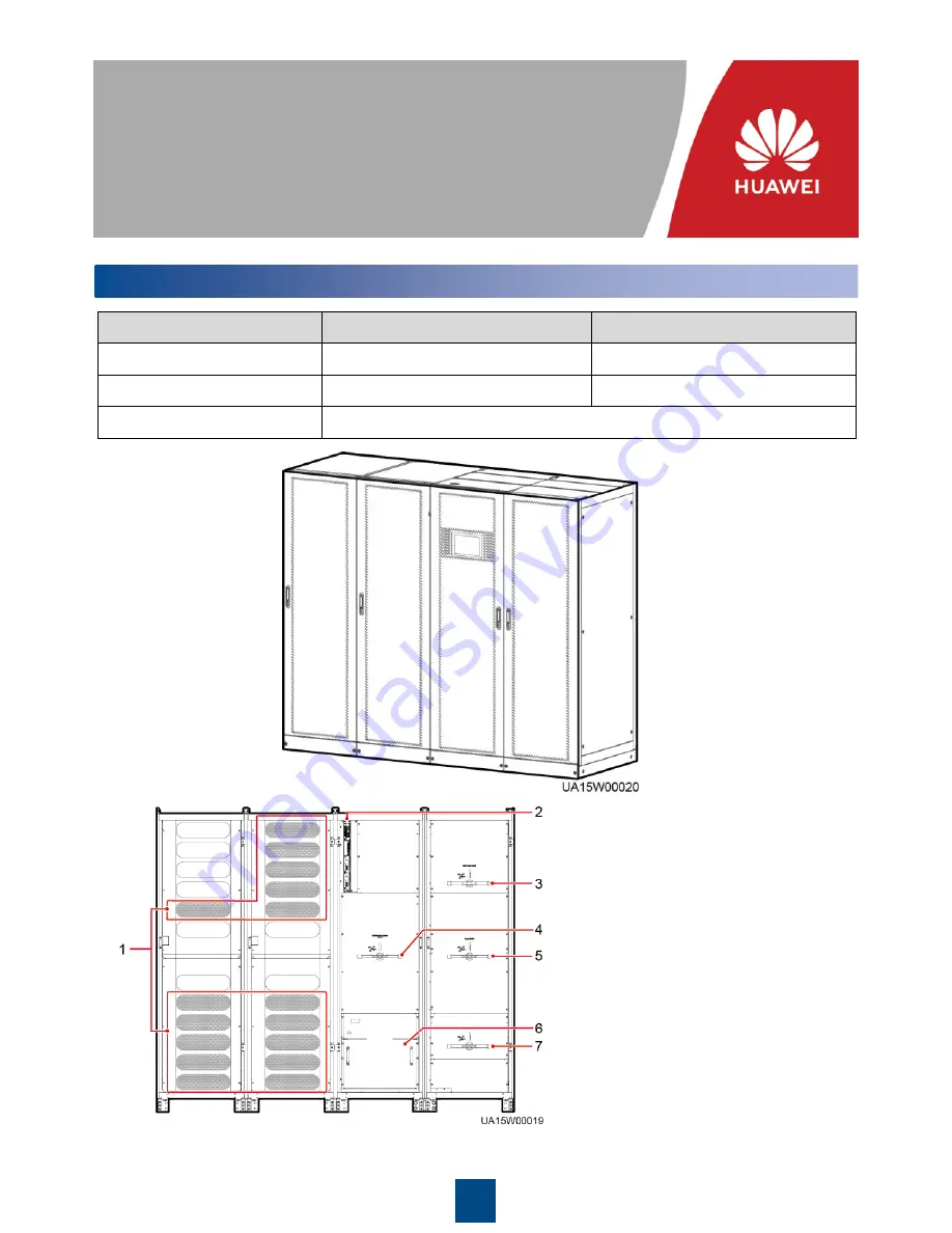
(1) Power unit
(2) Control unit
(3) Mains input switch (only available
in the full configuration model)
(4) Maintenance bypass switch
(5) Output switch (only available in the
full configuration model)
(6) Bypass unit
(7) Bypass input switch (only available
in the full configuration model)
Power
cabinet
Bypass
cabinet
Power
cabinet
Bypass
cabinet


