Huawei MA5833-BS60, Commissioning Manual
The Huawei MA5833-BS60 Commissioning Manual is available for free download on our website. This comprehensive manual provides step-by-step instructions on how to set up and optimize your Huawei MA5833-BS60 device. Get complete guidance and maximize the potential of your product with our user-friendly manual.
Share
Download


Reviews:
No comments
Related manuals for MA5833-BS60

FUSION Apollo MS-WB670
Brand: Garmin Pages: 44

CWD2005 SPC
Brand: Union Instruments Pages: 63

LONMSE 2M230I
Brand: WAREMA Pages: 4

Videobar VB1
Brand: Bose Pages: 2

Price Center 451
Brand: Polycom Pages: 4

65 41 2 163 268
Brand: BMW Pages: 16

MULTIFEEDER
Brand: btsr Pages: 73

CR-IR1001-15
Brand: Creator Electronics Pages: 52

GIOTTO 30-50 BT
Brand: BFT Pages: 21
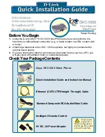
i2eye DVC-1000
Brand: D-Link Pages: 10

DA-E660
Brand: Samsung Pages: 27

AH68-01018B
Brand: Samsung Pages: 23

AH68-02275X
Brand: Samsung Pages: 29

AH68-00935B
Brand: Samsung Pages: 28

AH68-01236A
Brand: Samsung Pages: 28

AH68-01145B
Brand: Samsung Pages: 29

AH68-00939B
Brand: Samsung Pages: 29

CM3430B
Brand: Samsung Pages: 38


