For detailed installation, configuration and other information, refer to the hardware manual of the
controller you are using. See the
Additional References
section in this document.
1 SPECIFICATIONS
Table 1 – FOX104 / FOX404
Maximum number of stacks (total
number of hubs and bases)
5
Maximum number of cable drops to
any specific hub or base
3 (See Section Six for Example Setups)
Maximum length of Fiber Optic cable
10 Meters per Drop
Base ID#
Each Base or Hub must have a unique Base ID #.
Expansion I/O
EIAJ RC-5720 Plastic Fiber, TX+RX 10m per drop max host (OCS or
hub) to base
Type of Fiber Optic Cable
EIAJ RC-5720 (RC)
Primary Power
9-30VDC @ 400mA maximum
Power Draw
9-30VDC @ 400mA maximum
Height
4.25” (108 mm)
Width
6.63” (168.3 mm)
Mounting Depth
4.7” (119.4 mm)
Operating Temperature
32 - 122
°
F (0 - 50
°
C)
Humidity
5% to 95% non-condensing
UL
Class I, Groups A, B, C, D, Division 2
CE
Yes
2 INSTALLATION
2.1
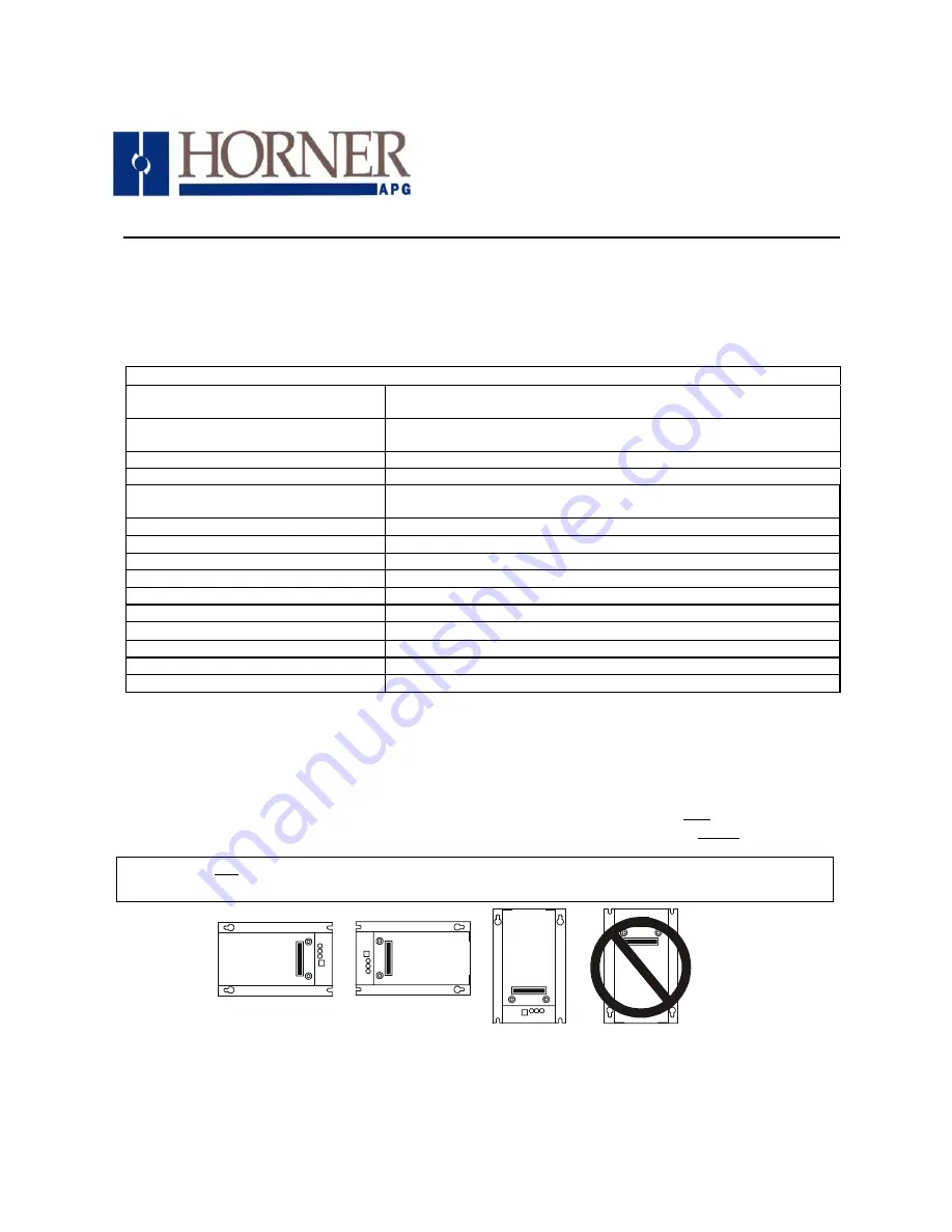
Mounting Orientation
The base of the FOX104 / FOX404 need to be mounted with the proper orientation. Proper orientation
helps to ensure a good connection when SmartStack Modules are installed. Up to four SmartStack
Modules can be installed per FOX104 / FOX404. The FOX104 / FOX404 is installed inside a panel box.
Figure1 – FOX104 / FOX404 Orientation
08
June
2005
MAN0508-03
Fiber Optic Extension System
HE800
FOX104 / FOX404
Products Specifications
and Installation Data
001FOX006
Caution: Do not instack more than four SmartStack Modules per OCS/RCS/FOX. Improper
operation or damage to the OCS/RCS/FOX and SmartStack Modules could result.