HORNER HE-XRC9, User Manual
The HORNER HE-XRC9 User Manual is an essential companion for mastering the functions of this remarkable product. This comprehensive manual is available for free download on our website, ensuring easy access to detailed instructions, troubleshooting tips, and valuable insights. Get the most out of your HORNER HE-XRC9 by referring to the user manual, conveniently accessible on manualshive.com.
Share
Download


Reviews:
No comments
Related manuals for HE-XRC9
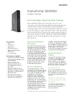
HomePortal 3801HGV
Brand: 2Wire Pages: 2

M40
Brand: Barracuda Networks Pages: 2

Arris SBG8300
Brand: SURFboard Pages: 13

COMSPHERE 392xPlus
Brand: Paradyne Pages: 285

Micromodem II
Brand: Hayes Microcomputer Products Pages: 39

BT4600
Brand: BlueTree Pages: 28

277 Series
Brand: 3onedata Pages: 3

F5D5530-W
Brand: Belkin Pages: 12

DI3652
Brand: Broadxent Pages: 40

E303
Brand: Huawei Pages: 3

OnCell G2111 Series
Brand: Moxa Technologies Pages: 49

S2 STICK
Brand: ZooZ Pages: 2

E842-DTU
Brand: Ebyte Pages: 17

InduBox GSM M4
Brand: Bausch Datacom Pages: 31

SCM4000
Brand: Microwave Radio Communications Pages: 274

MM340
Brand: Manta Pages: 2

PD60S
Brand: Paradise Datacom Pages: 4

06-5830
Brand: RaceAmerica Pages: 2


