Honeywell PRIMUS 1000, Pilot'S Manual
The Honeywell PRIMUS 1000 Pilot's Manual is a comprehensive guide for pilots operating this advanced avionics system. Packed with detailed instructions and essential information, this manual is available for free download at manualshive.com. Enhance your flying experience by accessing this user-friendly and informative resource.
Share
Download


Reviews:
No comments
Related manuals for PRIMUS 1000

CDF2001
Brand: Anvil Pages: 6

TMA44
Brand: trig Pages: 20

DENSEI MACHIDA FB-R5F11PLG
Brand: Naito Pages: 5
DULCE DCG 10
Brand: VALERA Pages: 2
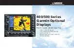
GPSMAP 400 series
Brand: Garmin Pages: 76

C3URHP
Brand: Igloo Pages: 14

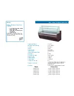
DL3M
Brand: Showcases Direct Pages: 7

Pi Touch Pro
Brand: Smarti Pages: 11
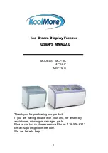
MCF-6C
Brand: KoolMore Pages: 5
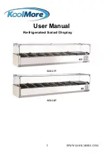
SCDC-7T
Brand: KoolMore Pages: 11


