background image


Honeywell Field Solutions 


MC Toolkit (MCT404) 

User Manual 


Doc. No.:   34-ST-25-50 

Revision 

Date: 

 June 2016 


Summary of Contents for MCT404

Page 1: ...Honeywell Field Solutions MC Toolkit MCT404 User Manual Doc No 34 ST 25 50 Revision 3 Date June 2016 ...

Page 2: ...es no express warranties except as may be stated in its written agreement with and for its customers In no event is Honeywell liable to anyone for any indirect special or consequential damages The information and specifications in this document are subject to change without notice Honeywell PlantScape Experion PKS and TotalPlant are registered trademarks of Honeywell International Inc Other brand ...

Page 3: ...ication software and FDC application software Revision Information Document Details MC Toolkit MCT404 User Manual Release Number Publication Date 34 ST 25 50 New Revision 1 February 2014 COM4 update Rev 2 May 14 STT 850 STT 750 added Rev 3 June 2016 References The following list identifies all documents that may be sources of reference for material discussed in this publication Document Title ...

Page 4: ...tandard Time Emergency calls outside normal working hours are received by an answering service and returned within one hour Email support Sales FP Sales Apps Honeywell com Technical Assistance hfs tac support honeywell com Mail Honeywell Process Solutions 1250 W Sam Houston Pkwy S Houston TX 77042 For other contact details in Europe Asia North and South Americas refer to the back page World Wide W...

Page 5: ...ro static discharge to which equipment may be sensitive Observe precautions for handling electrostatic sensitive devices Protective Earth PE terminal Provided for connection of the protective earth green or green yellow supply system conductor Functional earth terminal Used for non safety purposes such as noise immunity improvement NOTE This connection shall be bonded to Protective Earth at the so...

Page 6: ...404 product that includes MC Toolkit application and FDC application MCT404 Options include ruggedized version with no approvals Intrinsically safe version with Zone1 approvals Modem Honeywell HART DE modem that implements interfaces to the HART and DE network Offline The condition present when the MC Toolkit is running but is not connected to a live device Online The condition present when the MC...

Page 7: ...ansmitter Communication characteristics 5 Digital to Analog conversion and transfer 5 Honeywell Transmitter Analog Mode 5 Honeywell transmitter analog value scaling 8 Honeywell transmitter output Digital enhanced mode 9 2 3 Wi Fi Connection Support 12 3 GETTING STARTED 15 3 1 MC Toolkit Installation 15 3 2 MC Toolkit Assembly 16 MCT404 assembly 16 3 3 Safety instructions 18 For MCT404 18 3 4 Batte...

Page 8: ...g device history 56 Exporting device history records to FDM 57 Exporting device history records to Documint 58 Custom Views 58 4 7 Offline configuration 60 Overview 60 Importing offline configuration 60 Deleting offline configuration 61 Downloading an offline configuration 61 5 MANAGING DE DEVICES USING MC TOOLKIT SOFTWARE 63 5 1 Starting MC Toolkit application 63 5 2 Overview of MC Toolkit Homepa...

Page 9: ...shooting scenarios 124 6 3 MC Toolkit application software troubleshooting scenarios 128 MC TOOLKIT ERROR MESSAGES 129 DE Device error messages 133 Offline configuration Error Messages 135 7 MC TOOLKIT MAINTENANCE 139 7 1 MCT404 battery replacement 139 Battery Status 139 Battery Replacement 139 Charge the Battery 139 Replace the Battery 139 7 2 SD card replacement 141 MCT404 SD Card Replacement 14...

Page 10: ...vice health status 39 Table 8 Device configuration screen elements 41 Table 9 Device configuration screen icons 42 Table 10 Tool bar on graph chart page 52 Table 11 DE Displays Tasks Summary 73 Table 12 DE Upload Procedures 75 Table 13 DE Main Menu Procedures 77 Table 14 Input Calibration DE Transmitters 83 Table 15 Output Calibration Loop Test 88 Table 16 DE Output Calibration Trim DAC Current 90...

Page 11: ...numeric keypads 27 Figure 4 1 Generic layout of user interface 29 Figure 4 2 FDC homepage 30 Figure 4 3 Device homepage 38 Figure 4 4 Device configuration screen 41 Figure 5 1 Menu Tree Honeywell DE Displays 72 Figure 5 2 Offline Browse Open File dialog 100 Figure 5 3 MC Toolkit Options 101 Figure 5 4 DE device 102 Figure 5 5 STT25D and 25M STT350 models 103 Figure 5 6 STT25T model 103 Figure 5 7 ...

Page 12: ......

Page 13: ...perature etc that are available for use in the process control industry The emphasis of the information in this manual is directed primarily on the features and use of the MC Toolkit in performing common maintenance tasks relating to transmitter devices rather than on the features and installation of specific transmitter devices It is recommended that you should have the appropriate manuals availa...

Page 14: ...kit is available in high level model MCT404 MCT404 The MCT404 has following options Ruggedized version Environmentally hardened with no approvals Zone 1 approvals Intrinsically safe version available with FM Class I Div 1 IECEx and ATEX Zone 1 approvals Figure 1 1 MCT404 Ruggedized and Zone 1 Intrinsically safe models It includes the following components A PDA with integrated DE HART modem Honeywe...

Page 15: ... the transmitter is an element of a control loop the loop should be placed in the manual operating mode and alarms and interlocks trips should be disabled as appropriate before beginning the procedure The primary factors to be considered are separated into three categories under the following three headings The information under the following headings is intended as background for use of the DE Pr...

Page 16: ... augment the capability of a smart transmitter For this reason the calibration procedures in this MC Toolkit User Manual include a recommendation that the transmitter is removed from service and is calibrated only in a controlled laboratory environment using equipment whose precision is certified Software Environment MC Toolkit runs on the Windows Embedded Handheld 6 5 operating system A basic fam...

Page 17: ...de to ensure proper operation of the transmitter with all associated circuit components wiring power supply control equipment etc It is necessary to use precision test equipment an ammeter or a voltmeter in parallel with precision resistor The Trim DAC procedure is given in Table 16 The Apply Values procedure uses actual Process Variable input levels for calibrating the range of a transmitter To m...

Page 18: ...tion materials and to ensure that the calculated input is a high fidelity representation of the analog input linear or square root with a precise zero reference Input Calibration Corrects To optimize accuracy the PROM includes storage for calibration constants Correct Input Zero Correct LRV and Correct URV The corrects constants provide for optimum accuracy in that they enable fine tuning of the i...

Page 19: ... Signal Output The vertical scale at the left of Figure 2 2is an example of the available range LRL to URL of a pressure transmitter sensor as built and characterized at the factory The area of this scale that is highlighted in white represents the configured process operating range LRV to URV in this case from 100 in H2O to 225 in H2O Note that Engineering Units EUs shown in Figure 2 2 are includ...

Page 20: ...mmunications between the MC Toolkit and the Honeywell Smart Transmitter consist of digital pulse strings with rapid transitions of current level between approximately 4 mA and 20 mA CAUTION These rapid transitions provide for effective communications but will interfere adversely with a transmitter operating on line in a control loop The MC Toolkit communicates digitally exercise caution and good j...

Page 21: ...oneywell HART Transmitters Transmitters with HART capability have features that vary among manufacturers and with the characteristics of specific devices The FDC application supports the HART Universal Common Practice and Device Specific Commands that are implemented in Honeywell HART transmitters As the diagram in Figure 2 4 shows the Honeywell HART Transmitter is virtually identical to non HART ...

Page 22: ...ecific purpose are designed to common agreement standards that provide for inter operability Guidelines published by the HART Communication Foundation enables manufacturers to design devices that communicate via a set of standard commands and responses The FDC application software supports the HART Revision 5 0 6 0 and 7 0 commands that are exposed through the HART Communication Foundation Device ...

Page 23: ...ore you begin 2 2 Transmitter Communication characteristics Revision 3 MC Toolkit MCT404 User Manual 11 Figure 2 4 Honeywell HART Transmitter Diagram Figure 2 5 HART Point point and Multi Drop Value Scaling ...

Page 24: ...ort MCT404 is sold with or without Wi Fi option This section shows you how to connect the handheld to Wi Fi and then connect to the Internet for example to download the DD files for any Transmitter or connect to a network printer etc 1 Make sure the Wi Fi setting is Turned on 2 Set the Security Choice to Func Security ...

Page 25: ...nual 13 3 The IP address will be detected automatically If it is not detected then find the IP address from your network provider and enter it in the IP Address and Subnet Mask field 4 Select OK Once the IP address is entered you can connect to the network with or without DHCP Enabled ...

Page 26: ......

Page 27: ...tallation MC Toolkit software is fully loaded in the factory on all new orders The installation instruction for the above process is in document 34 ST 33 59 The above document is available at https www honeywellprocess com transmitter configuration tools and accessories mc toolkit ...

Page 28: ...3 Getting Started 3 2 MC Toolkit Assembly 16 MC Toolkit MCT404 User Manual Revision 3 3 2 MC Toolkit Assembly MCT404 assembly Figure 3 1 shows the MCT404 assembly Figure 3 1 MCT404 assembly ...

Page 29: ...s of MCT404 assembly Item Description Positive and negative test leads Connecting terminals for test leads Test leads to connect to the field device Functional keys which can be configured Navigational keys Button for powering on powering off the MC Toolkit Pin charging plug with USB connector Reset buttons For Soft Reset press both the buttons simultaneously ...

Page 30: ...1 20 areas Ensure that the MCT404 ZZ unit is not taken in to Ex area Electromagnetic waves which can arise with the i roc when using WLAN or Bluetooth functions can cause disturbances and endanger your health Since no definite statements can currently be made about the immunity from disturbances of heart pacemakers we recommend users of pacemakers to avoid using transmitters generally Do not trans...

Page 31: ...MCT404 User Manual 19 3 4 Battery and Power Supply For battery care of MCT404 refer to MCT404 battery replacement section 7 1 For the Power supply information for MCT404 refer to 300011CB02A01_instruction_manual_irocCi70 Ex_EN pdf that is shipped with the MCT404 product ...

Page 32: ...appears displaying the Start icon Shutting down the MCT404 Press the Power button on the MC Toolkit and hold it for few seconds to shutdown 3 6 Application icons Select on the Start icon All the available shortcuts will be displayed under the Start Menu as shown in Figure 3 2 Figure 3 2 Start Menu The icons for the two applications MC Toolkit and FDC are available directly under the Start Menu If ...

Page 33: ...t MCT404 Revision 3 MC Toolkit MCT404 User Manual 21 3 7 Connecting to a device through MC Toolkit MCT404 Figure 3 3 shows how a field device is connected through MCT404 Refer to the MCT404 assembly for more details Figure 3 3 Connecting to a device through MCT404 ...

Page 34: ...User Manual Revision 3 Wiring diagrams Figure 3 4 displays how to connect directly to the terminals of HART DE device Figure 3 4 MCT404 terminal connections to HART DE device Figure 3 5 displays connecting HART device with 250 ohm resistor Figure 3 5 MCT404 terminal connections to HART Device ...

Page 35: ...om keypad which supports numeric or alphanumeric keys depending upon the input context In the Keyboard method you select a text field in display and then selects a character at a time from a virtual keyboard Using the keyboard involves familiar concepts that will enable quick and accurate entries In the other three methods the stylus is used to write the desired input directly onto the screen and ...

Page 36: ...on the arrow at the bottom right corner of the display and tap on Block Recognizer 2 Use the stylus to provide a character input to the letter pad at the bottom of the screen The character strokes are then converted to typed text on the screen as shown below in Figure 3 7 Figure 3 7 Block Recognizer Note Tap on icon to view the help for using Block Recognizer and tap on icon to view the table of s...

Page 37: ...g letter recognizer perform the following steps 1 Tap on the arrow at the bottom right corner of the display and tap on Letter Recognizer 2 Use the stylus to provide character inputs between the lines which appear at the bottom of the screen The character input is recognized and displayed on the screen as shown in Figure 3 8 Figure 3 8 Letter recognizer ...

Page 38: ... transcriber perform the following steps 1 Tap on the arrow at the bottom right corner of the display and tap on Transcriber 2 Use the stylus to input the characters by writing them on the screen in cursive print or mixed handwriting The character input is recognized and displayed on the screen as shown in Figure 3 9 Figure 3 9 Freehand recognition ...

Page 39: ... methods Revision 3 MC Toolkit MCT404 User Manual 27 Input dialog in FDC Depending upon the context of the data FDC smartly presents an alphanumeric or numeric keypad for data entry as shown in Figure 3 10 Figure 3 10 Alphanumeric keypads ...

Page 40: ...ward through Menus NA F2 F2 Navigate Forward through Menus NA F3 F3 NA About MC Toolkit F4 F4 NA Exit MC Toolkit Application F5 F5 Shift F1 NA Modem Diagnostics F6 Shift F1 F6 Shift F2 Volume Up Volume Up F7 Shift F2 F7 Shift F3 Volume Down Volume Down F8 Shift F3 F8 Shift F4 NA File Options F9 Shift F4 Not Available NA Help Topics General F10 Shift F5 Not Available NA Help Topics DE Available in ...

Page 41: ...n the MC Toolkit refer to section 3 5 Start up Shutting down the MC Toolkit and 3 6 Application icons 2 Select FDC from the Start menu The FDC homepage appears Generic layout of user interface of FDC The FDC generic layout consists of title bar workspace and menu bar which appear consistently on all screens and the options may vary depending on the context and selection Figure 4 1 Generic layout o...

Page 42: ...page title Page icon Displays current page icon Icon 1 Icon 2 Exit button Tap to quit the current page Workspace Consists of various menu items for working with FDC Menu bar Consists of options for navigation and selection 4 2 Overview of FDC homepage The FDC homepage consists of links for Online Configuration Offline Configuration Manage DDs and Settings Figure 4 2 shows the FDC homepage Figure 4...

Page 43: ...ize FDC You can customize FDC for device detection DD selection and other application settings Device Identification Use the following options to configure FDC to identify a device COM Port It allows selection of COM port to which HART DE is connected Using Poll Address Use poll address 0 only Use this to detect a device with the poll address as zero Find first poll address and use Use this to det...

Page 44: ...uggested by Honeywell TAC because this may impact the application performance Manage DDs Using this feature you can manage the DD files installed with FDC A DD file contains descriptive information about the functionality of a device By default a set of DD files are installed with FDC However if you do not have a DD for a given device you can install it using the Add DD feature Similarly you can u...

Page 45: ...With this setting FDC will detect the first device which responds on any poll address during a scan from 0 to 63 To detect a device using selected poll address tap Use selected poll address and choose the appropriate poll address using the up and down arrow keys For example if you want to detect a device with poll address 20 press and hold the up or down arrow key until the poll address 20 appears...

Page 46: ...following steps 1 On the FDC homepage tap Settings Select The Settings dialog box appears 2 Tap Others tab 3 Select Low Storage Space Warning checkbox 4 Press and hold the up or down arrow keys to set the notification for percentage of available storage card space which is available For example if you want to set the percentage for notifying a low storage card space to 20 press and hold the up or ...

Page 47: ...as below Manufacturer Device Type DevRev xx DDRev yy DevRev pp DDRev qq Add a DD file To add a DD file for a device perform the following steps 1 From the FDC homepage tap Manage DDs Select The Manage DDs dialog box appears 2 Tap Options Add DD Or Tap The ADD DD files dialog box appears 3 Browse to the location in which the DD file fm8 is located and tap OK 4 If the DD file already exists then the...

Page 48: ...of the following ways a By device manufacturer Select a device manufacturer to delete all device types and DDs associated with the manufacturer s devices b By device type Select a device type to delete all DDs associated with the device c By device revision and DD revision Select the specific entry of device revision DD revision to delete the specific DD 3 Tap Options Delete DD Or Tap A confirmati...

Page 49: ...The DD library is now validated and refreshed 4 5 Overview of device configuration Device configuration is the process of setting the variables of a device to desired values Typically the configuration process is equated with the act of writing values to a device but procedurally it involves the following Identifying a device Reading observing device variable values Editing variables Sending edite...

Page 50: ...ication functions for you to perform these functions more conveniently Detecting and loading a device When you tap on Online Configuration the device detection and loading process automatically gets started Depending upon the Device Detection and DD Selection settings you may have chosen you may be prompted for certain inputs as described in the Settings section Overview of Device Homepage Once th...

Page 51: ...ts The number and labels on these entry points may vary from device to device as defined in the DD file Select this option to view the detailed status of the device with respect to the Communication Device Status and device specific diagnostic details Tap Methods List to view and execute methods Tap to close the device home page Note The entry points Device Status and Methods List appear for all d...

Page 52: ...t set standards and then tuning them to meet the desired limits Both these operations are enabled through editing and writing variables or executing well defined methods Monitoring is an operation which involves observing values of a set of variables This could be achieved simply by reading the variable values in different menu groups or through visual constructs such as Graphs Charts and so on Di...

Page 53: ... options in hierarchy as defined in the DD file Tap to search items in the current entry point for the device Tap to review and send edited variables to the device This becomes enabled only if at least one variable has been edited Bottom pane which consists of items corresponding to the selected menu Tap to return to Device homepage A Device Configuration page is split horizontally into an upper a...

Page 54: ...n tree Indicates a Method item Indicates a Variable item Indicates an Edit Display item Indicates a Grid item Indicates a Chart item Indicates a Graph item Indicates an Image item When you navigate to a specific menu in the top pane FDC displays the items under that menu in the bottom pane If the some of the items under the menu are variables or parameters then FDC also fetches their corresponding...

Page 55: ...desired menu The bottom pane will display items under that menu 5 Select an editable variable from the list Note An editable variable can be differentiated from a read only variable the read only variable is displayed in Grey text whereas an editable variable is shown in Black text 6 Tap Edit Note If the variable has been defined as a Loop Warning Variable then following dialog appears 7 Press Yes...

Page 56: ... edited variables perform the following steps 1 Tap to send the edited variables values to the device The Send to Device page appears This page allows you to review the values you have edited and provides you a choice to either send the values to the device or even canceling your changes To cancel your changes simply select a required variable and tap reset this action will restore the value of th...

Page 57: ...ual 45 If the variables are updated successfully to the device status appears as SUCCESS in green color and if failed status appears as FAILED in red color 5 Tap to close the current page and to return to the previous page Note Use to reset the selected variable s values Double tap on FAILED status to view the reason ...

Page 58: ... the Functions tab choose Online 2 Tap icon on the bottom left part of the page The Item Search dialog box appears 3 Under All or part of the item label tap 4 Enter all or part of the item label you want to search using the keypad 5 Tap OK 6 You can refine your search by selecting the type of item you want to search using Search In list 7 Tap Search 8 Under Results select any of the results 9 Tap ...

Page 59: ...there s more status available for the device these are the variables you should investigate for further details Perform the following steps to view the details of device health Note For example consider the following scenario 1 On the Device Home page tap Functions tab 2 Under the Functions tab choose Device Status The Device Status page appears 3 From the drop down list select any of the variable...

Page 60: ...se the View Legends dialog box 10 Tap Options Edit Waveform The Edit Waveform dialog box appears This lists the x y pairs for the waveform The non editable values are shown in grey 11 Select the required value and tap Edit The Edit Variable dialog box appears 12 Edit the value and tap OK to return to Edit Waveform dialog box Note The edited value is highlighted in yellow color 13 Tap Return to ret...

Page 61: ...ce Further a chart may have more than one source which you may select to view The colors labels and axes of charts may vary from device to device as defined in the DD file The rate at which the chart is refreshed is governed by the DD file The default refresh rate is 3 seconds The following are the types of charts Strip In a Strip chart data scrolls from right to left New data is updated at the ri...

Page 62: ...ical line separates the old data from the new and scrolls as the new data displays When the plot reaches the right most end of the chart the data begins plotting again from the left end of the chart Scope A Scope chart updates from left to right When the plot reaches the right most end of the chart the display is erased and the data begins plotting again from the left end of the chart ...

Page 63: ...dial type analog meter The indicator is a pointer that rotates as the current value varies with time Bar Charts A bar chart displays the device data in bars varying with time A bar displays values from bottom to top with its origin minimum value at the bottom of the chart Alternately a bar may also displays values horizontally from left to right with its origin minimum value at the left of the cha...

Page 64: ...page appears 6 Tap Options Select Source 7 The Select Source dialog box appears 8 Select the required source and tap OK to view the chart of the selected source 9 Tap Options View Legends 10 The View Legends dialog box appears with the legends 11 Tap Close to close the View Legends dialog box 12 Tap Return to close the chart page and return to the menu navigation view Note The following options ar...

Page 65: ...e Select 3 The Device Configuration page appears which displays the top and bottom panes 4 Navigate to the desired menu The bottom pane will display items under that menu Select any grid from the list of available grids which appear on the bottom pane 5 Tap View The grid page appears 6 Select a value and tap Edit The Edit dialog box appears Note The Edit option is enabled only if the value is edit...

Page 66: ... view an image perform the following steps 1 On the Device Home page tap Functions tab 2 Tap Online Select 3 The Device Configuration page appears which displays the top and bottom panes 4 Navigate to the desired menu The bottom pane will display items under that menu Select any image from the list of available images which appear on the bottom pane 5 Tap View The image page appears 7 Tap Return t...

Page 67: ...y items under that menu 5 Select a method from the list For example Loop Test 6 Tap Execute A warning message appears displaying a message that loop must be removed from the automatic control 7 Tap OK 8 The Loop Test dialog box appears displaying the information to choose analog output level 9 Choose the analog output level and tap OK Note To cancel the method execution tap Abort 10 A message appe...

Page 68: ...imes overwriting the existing one To save device history perform the following steps 1 On Device Home page tap Tools 2 Select Save History and tap Select The Save History page appears 3 Enter the History Record Name using the keypad and tap OK History Name field accepts alphanumeric characters underscore and no other special characters 4 Enter the Device Tag using the keypad and tap OK Device Tag ...

Page 69: ... named as per the following convention for the primary name DeviceTag_ManufacturerIDDeviceTypeDeviceRevisionDDRevision_DeviceID 4 Copy the desired Device History Record files with fdm extension from the above mentioned location to a temporary location on FDM Client computer 5 Use FDM Import Export wizard to import the history records into FDM After you import successfully The snapshot would get im...

Page 70: ...n a device and thus creating your own custom views This is a very convenient utility when you are interested in select few variables in a device and saves you the time for navigating through the menus You can create two views per device type with maximum of 10 variables selected for each custom view To create modify the custom views perform the following 1 On Device Home page tap My Views 2 Tap Co...

Page 71: ...plication Software 4 6 Online configuration Revision 3 MC Toolkit MCT404 User Manual 59 Note To view the custom views tap My View 1 Select The My View 1 page appears The editing and other features are as explained in the earlier sections ...

Page 72: ...the device Create offline configuration template in FDM Save the configuration in FDM in FDM format Import the offline configuration in FDC Download the offline configuration to the device Note For details on creating and using offline configuration refer to section Offline configuration in FDM User s Guide Importing offline configuration Using this feature you can import offline configuration tem...

Page 73: ...an offline configuration Using this feature you can download the offline configuration when the device is online To download an offline configuration perform the following steps 1 On the FDC homepage tap Offline Configuration Select The Offline Configurations page appears 2 Select the required offline configuration template from the list 3 Tap Options Download The Offline Select Variables page app...

Page 74: ...t of selected variables 7 Tap Send and the process to send the variables to the device starts Once the downloading is complete the following page appears Note If the variables are downloaded successfully status appears as SUCCESS in green color and if failed status appears as FAILED in red color 8 Tap Finish to return to FDC Homepage ...

Page 75: ...epage MC Toolkit Homepage allows user to select the Configuration Mode Online or Offline It also offers menu options File Modem and Help The details of the Menu are given under the Menu Bar topic Online and Offline Modes Online Online button allows you to establish connection to a device and allows following operations upload of the device database configuration of parameters Calibration and Diagn...

Page 76: ... a basic offline template edit the parameters and download to a device after establishing connection The updates to the parameters can also be saved into the file without actually downloading to the device Complete detail is provided under Offline Configuration section 5 6 MC Toolkit Power ON Allows DE Operating Procedures ...

Page 77: ...tions and HELP display table Back Button In general selecting the Back button at the bottom of any display will call up the previous display In most displays the Back button is at bottom right or bottom center When it appears at bottom left along with a left pointing arrow it indicates that selecting the Back button will necessitate a new Upload Menu Bar Menu Bar Menu Selections and HELP display M...

Page 78: ...5 3 MC Toolkit Application Software Display Conventions 66 MC Toolkit MCT404 User Manual Revision 3 Menu Bar Menu Selections and HELP display ...

Page 79: ...f COM4 Port Offline Configuration Options has Offline Configuration Settings The details will be under MC Toolkit Options dialog section File Online mode Exit Closes the MC Toolkit application Save to File Enables export of database parameters in XML format which can be used by other programs such as DocuMint Refer to the Reference Data section 5 8 for more information This selection is not availa...

Page 80: ...t BOTH Modem Battery and Modem Status are OK Do not continue in case of any bad status Modem Diagnostics Modem Battery Must display Ok to proceed Modem Version Current Modem firmware version on the xx xx form Protocol Always DE This information is for diagnostic purposes since the modem can handle both HART and DE protocols The Connection State may be Analog 4 Byte DE 6 Byte DE Modem status may be...

Page 81: ...erlined letters is selectable to provide direct access to the Help information Dragging the cursor in the scrollbar at right enables viewing of all three groups of topics At the bottom of each group a Back to Top selection moves the display to the beginning of the first group of topics Note The View Find and arrows selections at the bottom of the screen apply to the Help that applies to the Pocket...

Page 82: ...ground and arrow at right indicates a read write R W selection list The value previously selected and stored in memory is displayed Selecting the arrow at right presents a list of available selections and selecting an item from the list places it in the selection box If you exit the screen before using the Send button the changes will be ignored 4 The label above the box indicates the meaning of t...

Page 83: ...to establish connection to a device and do Online operations Online Mode Introduction This section contains procedures for using the MC Toolkit application software to communicate with Honeywell DE Transmitters On the Homepage select Online button to proceed with Online Configuration features For specific data relating to parameters involved in the procedures refer to Reference Data in section 5 8...

Page 84: ...5 5 Online configuration 72 MC Toolkit MCT404 User Manual Revision 3 Figure 5 1 Menu Tree Honeywell DE Displays ...

Page 85: ...ontent of each display is summarized in Table 11 Note Only the Basic display is available for the STT 750 Temperature Transmitter Table 11 DE Displays Tasks Summary Menu Item Task DEVICE INFO Enter Device Type Tag ID Message in Scratch Pad Observe Read Type Serial Number Firmware Version GENERAL Select PV Type Enter Comm Mode Line Filter STT T C Fault Detect STT Observe Read Failsafe Direction DE ...

Page 86: ...STT 850 750 Select read Write Screen Format PV Selection Screen Units Decimals Scrn Rotation Rotation Time Observe Read Display Type Sensor Input Sensor Mode STT850 ONLY Enter Read Write Bar Low Limit Bar High Limit Trend Duration MONITOR Observe Read Input value Output value Secondary Input value Gross Status code Device Status Messages Auxiliary Configuration STT 3000 Select Critical Status Latc...

Page 87: ...s Warning appears only if the transmitter is configured for operation in analog mode WARNING Before proceeding if the transmitter is part of a control loop ensure that interlocks and alarms are secured and that the loop is in Manual control Then select the OK button in the popup message The display at right appears Use this display to Verify device identification and to monitor Gross Status proces...

Page 88: ...5 5 Online configuration 76 MC Toolkit MCT404 User Manual Revision 3 DE Upload Procedures ...

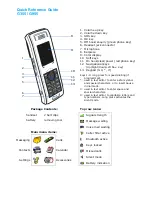
Page 89: ...nu to navigate to different screens Save to File allows saving the current device configuration to a file More detail on this under Save To File in Online Mode Procedure Device Info Type field will show ST 800 when ST 800 device is connected Tag ID r w User ID up to 8 alphanumeric characters suggestion relate to functional process entities and or plant areas Type r Manufacturer s device type ident...

Page 90: ...ST 3000 ST 800 STT 3000 LRL r Lower Range Limit URL r Upper Range Limit LRV r w Lower Range Value URV r w Upper Range Value PV Units r w Selection of scaling value default inches of H2O 39 F SV Units r w Selection of scaling value C F Sensor Type r Sensor Type associated with the transmitter Damping r w Selection of level of digital noise reduction Span r Process Range URL LRL Conformity r w ST 30...

Page 91: ...for Flow Upper Value Flow EU Lower Value r w Selection of standard Engineering Units for Flow Lower Value Local Meter ST 3000 example Local Display ST 800 Display Hardware r Type designation of display associated with the transmitter Display Units r w Selection EUs for Local Display Custom Units r w Refer to Transmitter User Manual Flow EU Upper Value r w Selection of standard Engineering Units fo...

Page 92: ...for only Advance Display STT850 only Horizontal Trend Applicable for only Advance Display STT850 only PV Selection For Dual input Models Loop PV C F R K Ohm MV CJ Temperature C F R K Sensor 1 C F R K Ohm MV Sensor 2 C F R K Sensor Delta C F R K Sensor 1 Resistance Ohm Sensor 2 Resistance Ohm Loop Output mA Percent Output PV Selection For Single input Models Loop PV CJ Temperature Sensor Sensor Res...

Page 93: ...Configure Critical Status Latching Select Enabled or Disabled NAMUR Select Enabled or Disabled Disable requires that Write Protect is set to Not Write Protected CJ Temp Enter External Cold Junction Temperature Select the Read HI LO button to call up the READ HIGH LOW PV display Select the Read button to display the lowest and the highest PV values since last read Monitor Input r Sensor input in En...

Page 94: ...electing Yes adds the current online configuration into the current working file Selecting No brings up the Save As screen The location and folder are set to SD Card and CFG_MCT You can type in a new name for the file The default name will be New1 The configuration will be saved in the xml file under SD Card CFG_MCT folder on your MC Toolkit MCT 303 You can copy the saved configuration file to PC ...

Page 95: ...ertical positioning of the response profile The LRV Correct and URV Correct procedures establish the correct slope of the response profile in the process operating range by rotating the response profile around the zero reference point as a pivot The Zero Correct procedure can be done at any time during the Correct LRV and Correct URV procedures in the same calibration session The Correct LRV and C...

Page 96: ...nication between the transmitter and the MC Toolkit If a Honeywell Pressure Transmitter is being calibrated positioning leveling is important because the meter body contains fluids that can affect zero sensing Enter configure values for LRV and URV From the DE MAIN MENU select Configure to call up the DE CONFIGURE display a Use the PV Units to select the appropriate Engineering Units b Using the k...

Page 97: ... such as zero pressure e g vent both sides of a DP transmitter As indicated below this procedure will shift the slope up or down to eliminate the error at the zero reference The slope angle of the response is unchanged Select Yes in the message box above this message appears At this point ensure that the value of the PV applied at the input is exactly Zero Then select the OK button in the popup me...

Page 98: ...000 Select the Correct LRV button This message appears Adjust the input temperature to the exact value of the LRV entered in the DE CONFIGURE display Select the OK button this message appears Select the OK button to acknowledge Correct Input at URV ST 3000 ST 800 Select the Correct URV button This message appears Adjust the PV input pressure to the exact value of the URV entered in the DE CONFIGUR...

Page 99: ...his function commands the transmitter to overwrite all user input corrections with factory default characterization values It is intended for use only when excessive corrections render the transmitter inaccurate If corrects should not be overwritten with factory values select the No button If corrects need to be overwritten select the Yes button The timer will appear briefly indicating the operati...

Page 100: ... Test In the Output Calibration box select the Loop Test button the display at right appears Select the desired constant level Output 0 100 or Other any of 0 100 Select the Set button Select the Yes button and observe the output current at 0 100 or Other user entered Note If the transmitter is in Analog mode you can observe the output on an externally connected meter or on a Local Meter In DE Mode...

Page 101: ...elected as above in the CONFIRM Pop up message it is possible to exit MC Toolkit application while the Output is fixed at constant current This message at right appears if you perform an operation on the MC Toolkit that will terminate the connection to the transmitter while the transmitter is in output mode Select Yes button only if constant current Output with the MC Toolkit is intended Otherwise...

Page 102: ...ives For a DE transmitter operating in analog mode in a user s application calibrate the analog output current to the PV input range That is adjust the output such that 4 mA corresponds to 0 LRV and 20 mA corresponds to 100 URV Call up display In the DE MAIN MENU select the Calibration button The CALIBRATION menu appears Select the Trim DAC Curr button this display appears ...

Page 103: ...is high tap on the Decrement button and observe the change on the meter NOTE If the error is large you can accelerate the adjustment rate by changing the Step Size to 10 or to 100 When the zero current level 4 mA is achieved select the Set Output To 100 button NOTE On the voltmeter 20 mA corresponds to 5 volts Use the Increment and or Decrement buttons to adjust the output current to 20 mA When th...

Page 104: ...o 100 and apply this value to Set URV NOTE This procedure applies to DE Transmitters operating in DE Mode as well as to those operating in Analog current Mode On the DE MAIN MENU select the Calibration button In the Apply Values group select the Set LRV button The popup message at right appears Note The value of the Input indicated in this message updates only when the popup message is called up T...

Page 105: ...yed value is satisfactory select Yes to copy the Input Value to the LRV in the transmitter If not select NO and repeat this step Set URV While observing the PV value at the physical process element using a sight glass for example adjust the process variable to the desired Maximum level then select Set URV If the displayed value is satisfactory select Yes to copy the Input Value to the URV in the t...

Page 106: ... file and Import to Excel 1 Setup Activesync connection between your PC and MC Toolkit 2 Right click on ActiveSync icon on the System trey and select Explore 3 Select My Windows Mobile Based Device SD Card CFG_MCT XML file that you would like to copy to the PC 4 Right click on the file and select Copy 5 Go to a location on the PC for example c MCT ...

Page 107: ...ow to view the Saved Configuration file and Import to Excel Revision 3 MC Toolkit MCT404 User Manual 95 6 Right click and select Paste Now you can double click on the xml file to open in the Internet Explorer Browser The Configurations are shown as below ...

Page 108: ...5 6 How to view the Saved Configuration file and Import to Excel 96 MC Toolkit MCT404 User Manual Revision 3 ...

Page 109: ...d Import to Excel Revision 3 MC Toolkit MCT404 User Manual 97 How to Import the data from the xml file to Excel 1 Open Microsoft Excel 2 Select Data Get External Data From Other Sources From XML Data Import and Browse to the xml file you saved on your PC This will Import data in the below format ...

Page 110: ...5 6 How to view the Saved Configuration file and Import to Excel 98 MC Toolkit MCT404 User Manual Revision 3 This can be saved as an Excel file for further file management ...

Page 111: ...On the MC Toolkit Home page select Offline to proceed with Offline Configuration features Offline configuration supports the following features File Management Open an XML file select a saved configuration for the selected device and edit the parameters Save to File Save the parameters back to the file Download Download current Offline configuration to a device after establishing connection The fo...

Page 112: ...urations for all the supported DE devices The available configurations can be updated and saved back to this file The TEMPLMCT XML is a Template file and you cannot edit the configuration in this file To read more about the Template file refer the section Template File Figure 5 2 Offline Browse Open File dialog The file lists all the configurations available for Honeywell DE devices Back button ta...

Page 113: ...creen The menu is available on the MC TOOLKIT screen and all of the File Management screens The Options dialog provides General Options and Offline Configuration Options Figure 5 3 MC Toolkit Options General Options Serial Port allows you to choose from any of the COM1 through COM8 ports Currently the Pocket PC supports only the COM1 port This option is only for future extension Offline Configurat...

Page 114: ...2 MC Toolkit MCT404 User Manual Revision 3 Parameters screens To access the parameters screens select one of the 3 buttons under the Edit Parameter Set caption on the Select Device type dialog Parameter set 1 Figure 5 4 DE device ...

Page 115: ...evices using MC Toolkit Software 5 7 Offline Configuration Revision 3 MC Toolkit MCT404 User Manual 103 Parameter set 2 Figure 5 5 STT25D and 25M STT350 models Figure 5 6 STT25T model Figure 5 7 ST 3000 ST 800 models ...

Page 116: ...the parameters screens Select the Save button to save the changes to the database Select the Undo button to undo the last change Depending upon the parameter a group of related parameters will be undone on selecting the Undo button Also depending upon the parameters changed the Undo button will be disabled when the Undo option is not appropriate To go back to the previous screen select the Back bu...

Page 117: ...nual 105 Save to File in Offline Mode Selecting Yes adds the current configuration into the current working file Selecting No brings up the Save As screen The location and folder are set to SD Card and CFG_MCT You can type in a new name for the file The default name will be New1 Figure 5 11 Save As File dialog ...

Page 118: ...ell DE Save Template Screen Figure 5 12 Honeywell DE Save Template Screen The user can select Yes to save the Template file as the working copy by giving a new name other than TEMPLMCT XML in the screen below Figure 5 13 Offline Honeywell DE Save Template as working file In the Working File Name field enter a file name other than TEMPLMCT XML without any extensions and then select OK The newly nam...

Page 119: ... to the device Connect the PPC to the modem with the serial cable and connect the modem to the device Select DOWNLOAD to Device to establish connection to the device and Download the selected configuration to the connected device Download confirmation screen will be displayed as in Figure 5 14 Download in Offline Mode Figure 5 14 Download in Offline Mode ...

Page 120: ...6 Transfer Function in ST devices Linearization in STT devices ST Linear and Square root STT Linear and Non Linear R W 7 LRV 36 98 R W 8 URV 594 63 R W 9 PV Units 0 R W 10 Output Range Out Low 4 R not displayed on the screen 11 Output Range Output High 20 R not displayed on the screen 12 Output Range Out Units ma R not displayed on the screen 13 OEM Device Type Code 23 STT25M S v1 5 T v0 DE R Not ...

Page 121: ...Device LRL DE Float DE R not displayed 22 Device URL DE Float DE R not displayed 23 SV Units 0 R W 24 Break Detect 1 R W depends upon the device 25 Critical Status Latching 0 R W depends upon the device 26 CJ Comp 0 R W depends upon the device 27 Device LRV DE float R not displayed 28 Device URV DE Float DE R not displayed 29 URL Range DE Float DE R not displayed 30 DE STT250 Type DE 0 0 1 or 2 R ...

Page 122: ...in STT LRV Transmitter input low in engineering units floating point URV Transmitter input high in engineering units floating point PV Units STT only C F R K PV Units ST Only inH2O 39 F inH2O 68 F MmHg 0 C PSI KPa MPa mBar bar g cm kg cm inHg 32 F mmH2O 4 C mH2O 4 C ATM inH2O 60 F Output Range Out Low Not displayed on the parameter screen Transmitter output low in percent floating point Output Ran...

Page 123: ... J T C K T C T T C S T C R T C E T C B T C N RTD PT100J Millivolts RTD PT100D RTD PT200 RTD PT500 RTD Ni500 RTD Cu10 RTD Cu25 T C RH Radiamatic T C W5W26 T C W3W25 Ohms T C NiNiMo Sensor Type ST only DP AP GP Line Filter STT only 50 Hz 60 Hz Scratch pad 32 chars Last Cfg Update Time Stamp in Date and Time format string SV Units C F T C Fault Detect Disable Enable Critical Status Latching Enable Di...

Page 124: ...vide 0 4 mA and 100 20 mA for testing proper operation of all components of the current loop LRL Lower Range Limit Minimum value in the useful range of the physical property of a transmitter at which a sensor can operate LRV Lower Range Value Minimum value in a continuous range of normal process values Match PV s Toggle for PV Matching When On the value of PV2 is set to the value of PV1 Meter Unit...

Page 125: ...r can operate URV Upper Range Value Maximum value in a continuous range of normal process values SEND Command from the HHC to copy the values of displayed parameters to either the transmitter to which it is connected or to NV memory in the HHC XS Delta Detection Toggle for Delta Alarm enabling If XS Delta Detection is On and the Delta Alarm value is exceeded the PV output goes to the Failsafe valu...

Page 126: ...n Upscale Downscale Line Filter STT only 50 Hz 60 Hz T C Fault Detect STT only Enabled Disabled DE Configure LRL URL LRV URV Floating point PV Units STT only C F K R PV Units ST only inH2O 39 F inH2O 68 F MmHg 0 C Psi KPa MPa mBar bar g cm kg cm inHg 32 F mmH2O 4 C mH2O 4 C ATM inH2O 60 F SV Units C F Sensor Type STT only T C J T C K T C T T C S T C R T C E T C B T C N RTD PT100J Millivolts RTD PT...

Page 127: ...oint Write Protection Enabled Disabled Password Write protection password 4 digits Change Password STT only New Password 4 digits Confirm New Password 4 digits Monitor Input Transmitter input in engineering units floating point Output Transmitter output in percent floating point SV Secondary variable floating point Device Status Gross Status Critical Non Critical Invalid Database Critical Critical...

Page 128: ...Display STT 850 STT 750 Display Type Not Connected Advance Display STT850 only Basic Display Input Model Sensor Input Single input Dual input Loop Mode Sensor Mode Sensor 1 Redundant Mode Delta Mode Screen Format View display format None Large PV Bar Graph Applicable for only Advance Display STT850 only Horizontal Trend Applicable for only Advance Display STT850 only PV Selection For Dual input Mo...

Page 129: ...Milliamps Decimals Number of digits to display after the decimal point x x x x xx x xxx Display Lo Lim STT850 only Display Low Limit for Trend Bar Graph usually equal to LRV Floating point value Display H Lim STT850 only Display High Limit for Trend Bar Graph Usually equal to URV Floating point value Trend Duration Optional STT850 only Duration of the trend screen in hours Valid range 1 999 Scrn R...

Page 130: ...on and are disabled as listed in Table 3 Configuring Display Common Parameters There are two common parameters that are currently configurable Scrn Rotation Screen Rotation Rotation Time If any of these 2 parameters are changed these parameters will be sent to the device first followed by the Screen parameters if any of those Screen parameters are changed If only the Screen parameters are changed ...

Page 131: ...n Rotation is Disabled then selecting Screen format to None will remove the currently active ScreenX and will bring Screen X 1 as the active screen PV Selection and Units Select any of the PV Selection options for Dual input mode with the available Units options Loop PV C F R K Ohm MV CJ Temperature C F R K Sensor 1 C F R K Ohm MV Sensor 2 C F R K Sensor Delta C F R K Sensor 1 Resistance Ohm Senso...

Page 132: ... the local buttons on the display selecting Disable will make the currently active ScreenX to stay as your top screen When the Screen1 is configured from MCT404 to see the Screen1 with the changes user needs to Enable the rotation Screen Rotation Time Select value of 3 to 30 seconds for the formatted screens to rotate Note that if there is any diagnostics then the diagnostics will alternately show...

Page 133: ...ld name Input Range In High 328 07 Field Field name Input Range In Units 0 Field Field name Output Range Out Low 4 00 Field Field name Output Range Out High 20 00 Field Field name Output Range Out Units mA Field Field name OEM DevType 23 ST 3000 S vB 6 T v0 Field Field name LRL 0 0 Field Field name URL 400 0 Field Field name Damping 0 00 Field Field name SensorType 0 Field Field name LineFilter 0 ...

Page 134: ...404 User Manual Revision 3 Field name DevLRV 0 00000 Field Field name DevURV 0 82018 Field Field name URLRnge 400 00000 Field Field name DESTT250Type 0 Field Record Table Database The Field names are explained in section Download Parameter List ...

Page 135: ... 6 1 MC Toolkit troubleshooting scenarios MCT404 Start up scenario Problem No DE HART Modem detected Cause The cause may be any one of the following MCT404 battery charge is low Resolution You can resolve by performing the following Refer the Battery Care section ...

Page 136: ...rm Refresh DD Library operation This will synchronize the DD library Device identification Problem When you tap Online Configuration option the application displays Device identification failed message and returns to home page Cause The cause may be any one of the following By default the application is configured to scan the device with specific poll address If the connected device has different ...

Page 137: ...xecution Problem Internal Error This method has some constructs which are not supported Cause The cause may be any one of the following Some internal error Method code has some error FDC encountered some construct that s not supported Resolution Retry executing the method If the problem persists please contact Honeywell TAC Graphs and Trends Problem Sometimes on selecting another waveform or varia...

Page 138: ...s are not valid in the device at that instance of time Resolution This is the expected behavior as per the standard Close device Problem Application shows error message while closing the device screen It is rarely observed scenario Cause The cause may be any one of the following Application might have run out of memory Resolution There is no impact of this error on further device operation User ca...

Page 139: ...ing DD file for the device is missing in FDC library Resolution Add appropriate DD file Interoperability with FDM Problem Date fields show incorrect date after importing history record to FDM Cause Regional settings is mismatch Resolution Change the regional setting to English United states in FDC PDA and in FDM machine Then retry saving history again in FDC and re importing in FDM ...

Page 140: ...talled in device memory instead of SD card One or more dependent files are corrupt Resolution You can resolve by performing the following Re installing MC Toolkit in SD card Launching Help Problem Unable to launch MC Toolkit Help Cause The cause may be any one of the following MC Toolkit application along with the Help files are installed in device memory instead of SD card One or more dependent f...

Page 141: ...eset See your Pocket PC documentation reset the unit Error writing to Com Port Error associated with the Communication port Error writing to Com Port Error associated with the Communication port EscapeCom function Error Error associated with the Communication port GetCommState Error Error associated with the Communication port Host Failed to get good response from the Modem Error associated with t...

Page 142: ...lem between the Pocket PC computer and the modem Repeat the command again Message length is shorter than expected Communication interruptions between Host Pocket PC and the modem Modem bad checksum Erroneous data packet received at the modem This could indicate a defective modem Repeat the command again If the problem persist contact Honeywell TAC Modem Buffer overflow Data bytes from Host Pocket ...

Page 143: ...l port Make sure ActiveSync Mobile Device Center is not running If Several programs are active try closing one or more open programs Stop the MC Toolkit application by doing File Exit and restart the program Use the Pocket PC hardware reset See your Pocket PC documentation reset the unit Caution If the Symbol PPT 2800 computer is reset it will lose all its installed programs and data The program w...

Page 144: ... Modem Present Could not recognize the presence of the modem HARTDE Modem Protocol set failed Host pocket PC to Modem communication failed Error In Communication with Device Closing the Device No Device found Do You want to Retry Could not establish connection to a transmitter If the above things are perfect try to change different device detection options from Preference dialog box under Device P...

Page 145: ... message to transmitter Retry the action again Invalid operation on Write Protected Field Attempt to write to a protected field Remove the Write protection if you are the authorized person by providing the right password and disabling the Write Protect mode Undefined Gross Status Byte from the Transmitter The transmitter has reported a status indication not understood by MC Toolkit Retry the opera...

Page 146: ...o return Are you sure you want to do this A new Upload will require approximately 60 second wait Same as Description Put loop in Manual Trips secured Changing values of transmitter parameters can cause process upset Same as Description Conformity must be square root to select this unit Units for Flow indications are available only when Square Root conformity is selected Same as Description Are you...

Page 147: ...elected On the Select Device Type dialog if no items are selected in any of the 3 List boxes Select Device Type Select Revision and Select Tag ID you get this message on selecting Edit Offline Params button Same as description Memory Allocation Error If any of the Dynamic memory allocation fails you get this message Try removing files that are not needed from the SD Card Do you want to save your c...

Page 148: ...ile Make sure the configuration file is not corrupted Reinstall the MC Toolkit if the problem persists Could not set Tag ID Do you want to proceed with the rest of the download When the Write Tag ID command fails you get this message You can abort the rest of the download or continue Same as the description Could not set Line Filter Do you want to proceed with the rest of the download When the Wri...

Page 149: ...escription No Device Types found Please make sure that you have selected the right Config File The file selected may be the wrong one Also if you are in DE mode and you select a file with no Configuration for the DE devices then you get this message Similarly if you are in HART mode and you select a file with no configuration for the HART devices you get this message Same as the description Lower ...

Page 150: ...g ID Same as the description Are you sure you want to leave the Device List screen You get this message when you select Back button on the HART Device List screen This screen lists all the devices on the HART network If you select to go back to the previous screen without doing download the program needs to poll the network again to list the devices Same as the description Are you sure you want to...

Page 151: ... your MCT404 for the first time Battery care Refer the About Battery Life and Conservation section of the 300011CB02A01_instruction_manual_irocCi70 Ex_EN pdf that is shipped with the MCT404 product Replace the Battery If your battery power is low you need to either charge the battery in the MCT404 or replace it with a charged battery 1 Save your files and close any open applications 2 Press the Po...

Page 152: ...7 1 MCT404 battery replacement 140 MC Toolkit MCT404 User Manual Revision 3 Figure 7 1 Remove Handstrap Figure 7 2 Remove Battery Cover ...

Page 153: ...l software The MCT404 supports an optional 32 GB maximum capacity SD card 1 Press the Power button to turn off the MCT404 2 Remove the handstrap and the battery See Figure 7 1 3 Remove the four Phillips screws and open the card access door 4 Slide the SIM card door to the left to unlock it and open the door 5 Slide the SD card door towards the top of the computer to unlock it and open the door ...

Page 154: ... SIM card door and slide it to the right to lock it in place 3 Close the card access door Then replace the cover plate and fasten the four screws 4 Install the battery Press down firmly on the bottom of the battery Then tighten the screw 5 Reattach the handstrap 6 Press the Power button The MCT404 cold boots Note The MCT404 resets when you open the card access door to insert the SD card Make sure ...

Page 155: ...e Center connection Connect the ActiveSync Mobile Device Center cable from the PDA base to a USB port on the PC ActiveSync Mobile Device Center should start automatically If your PDA is synched with the PC you see the Screen Y If the screen does not come up maximized you will see the icon on your Desktop Taskbar Double tap on the icon to maximize Figure 8 1 Screen Y ...

Page 156: ...hed up with your PC and you will see the screen below Select File Connection Settings and set the Connection settings as below Select OK The Synch process should start now If you are still not connected then Soft Reset the PDA with the Sync cable still connected between the PDA base and the PC This should automatically establish synch connection between the PDA and the PC and you should see the Sc...

Page 157: ...start automatically If your PDA is synched with the PC you see the screen below If the screen does not come up maximized you will see the icon on your Desktop Taskbar Tap on the icon to maximize Figure 8 2 Screen X You can proceed with the MC Toolkit Installation following the Instructions on the 34 ST 33 58 If you do not see the Screen X select Start All Programs Windows Mobile Device Center It i...

Page 158: ... Connection settings as below Select OK The Synch process should start now If you are still not connected then Soft Reset the PDA with the Sync cable still connected between the PDA base and the PC This should automatically establish synch connection between the PDA and the PC and you should see the Screen X ...

Page 159: ...s editing and saving the Offline Configuration parameters back to the file applicable to DE devices using MC Toolkit application Save History Allows saving current Online configuration as a History file within the PDA applicable to Universal HART devices using FDC application Send Allows writing changes to one or multiple parameters in the Device in Online Mode Download to Device In MC Toolkit app...

Page 160: ...mation such as Contacts and Tasks as well as software upgrades IrDA Port Location IrDA Port Figure 8 4 MCT404 Infrared port location Provisioning Before the transmitter can be configured it must be unlocked with a security key so it can join the network Use the Provisioning Device Pocket PC software to receive security keys from the Key Server manager then aim the Pocket PC at the transmitter and ...

Page 161: ...ing Device Prerequisite AcitveSync should be installed on the clients PC connected to WDM Active Sync software is usually shipped on a CD along with the Provisioning Device Active Sync software can be downloaded from Microsoft Provisioning Device should have NET Compact Framework Installed NET Compact Framework can be downloaded from Microsoft Run msi on PC it will install framework on PDA Provisi...

Page 162: ...n copy cab from PC to PDA Click cab file to install the cab file on the PDA Writing Provisioning Information Provisioning Device Name Unique name up to 32 characters long Number of keys Maximum number of keys is 100 Expiration maximum number of days that the keys may be valid is 31 Sending Provisioning Information Select WDM in selection panel expand Provisioning Enter name Number of Keys Expirati...

Page 163: ...alue set according to its Model Number and this value is consistent with those values given in Table 7 4 The TX Power setting may be changed via the Authentication Device when a special application app is installed This app is considered to be Honeywell sensitive material and is made available only to the qualified Professional Installer Due to radio approval body regulations changing the TX Power...

Page 164: ...C Toolkit MCT404 User Manual Revision 3 9 Appendix B 9 1 MCT Power Save Guidelines When not in use always turn off the PDA Do not leave the MC Toolkit or FDC applications running if not in use exit the applications to save modem battery ...

Page 165: ...tation 50079567 002 Power Cord US 50079567 003 Power Cord EU 50079567 004 Power Cord UK 50079567 005 Power Cord AU 50079567 006 Docking station Power Supply and USB cable for computer interface 50079567 007 Stylus for the MCT404 Touch screen 50079567 008 Transmitter connector cable with one set of Alligator Clips and one set of EZ Clips 50079567 009 Spare Battery 50079567 010 Leather carrying case...

Page 166: ...SIA PACIFIC Honeywell Process Solutions TAC hfs tac support honeywell com Australia Honeywell Limited Phone 61 7 3846 1255 FAX 61 7 3840 6481 Toll Free 1300 36 39 36 Toll Free Fax 1300 36 04 70 China PRC Shanghai Honeywell China Inc Phone 86 21 5257 4568 Fax 86 21 6237 2826 Singapore Honeywell Pte Ltd Phone 65 6580 3278 Fax 65 6445 3033 South Korea Honeywell Korea Co Ltd Phone 822 799 6114 Fax 822...

Reviews: