Honeywell LTE-X series, Installation And Setup Manual
The Honeywell LTE-X series boasts a cutting-edge wireless communication system that seamlessly integrates with your devices. Ensure flawless installation and setup with our comprehensive Installation And Setup Manual, available for free download from our website. Experience superior connectivity and stay ahead with Honeywell LTE-X series.
Share
Download


Reviews:
No comments
Related manuals for LTE-X series

GT-I6410
Brand: Samsung Pages: 72

GT-I8510/8
Brand: Samsung Pages: 33
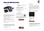
realpresence trio 8800
Brand: Polycom Pages: 7

Smartphone E-11
Brand: Etisalat Pages: 75

C790
Brand: Pantech Pages: 66

CX 200
Brand: Polycom Pages: 4

TALK 5H
Brand: WayteQ Pages: 24

SGH-a887 Series
Brand: Samsung Pages: 190

SGHC207
Brand: Samsung Pages: 219

Linemex ISDK Series
Brand: Uniphone Pages: 25

CL8500
Brand: Geemarc Pages: 70

CL8360
Brand: Geemarc Pages: 76

GM 20
Brand: GENERAL MOBILE Pages: 16

Z6530V
Brand: Zte Pages: 23

Z2
Brand: Sharp Pages: 20

Vodafone 802SH
Brand: Sharp Pages: 121

WX-T81
Brand: Sharp Pages: 150

WX-T92
Brand: Sharp Pages: 170


