background image


43-TV-33-56   iss.4   GLO   Aug 19   UK 


TrendView recorders - Installation Instruction 


Analogue In / Analogue Out / Pulse Input cards / Alarm Relay 
and Digital Input / Output cards 
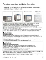
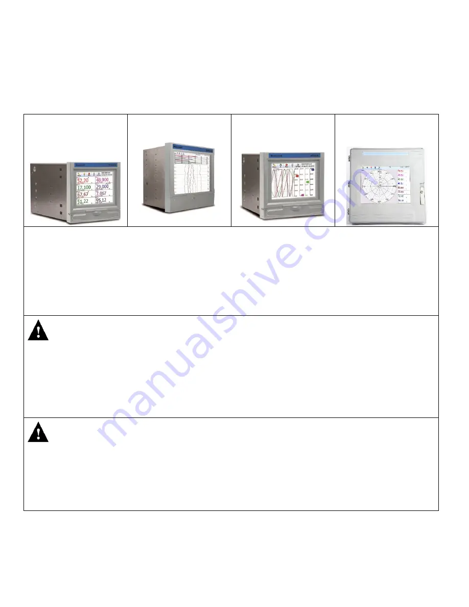
 

Minitrend Recorder 


Multitrend Recorder 


eZtrend Recorder 


DR Graphic 

Recorder 


This Installation Instruction sheet is intended as a guide for replacing or installing hardware and for setting up 
functionality in the recorder. Refer to the User manual for detailed operational requirements.   
The Minitrend, Multitrend, eZtrend and DR Graphic recorders are designed for ease of assembly with minimal 
disturbance to the rest of the unit. If unsure, please return the unit to your supplier for repair or upgrade. 
Removing the case and opening the back of the recorder should only be performed under the following circumstances: 
When an item of hardware requires individual replacement. 
When an item of hardware is to be retrospectively fitted. 
In all other instances, it is recommended that the complete unit be returned to an authorised agent or service centre. 
For Agency Approved recorders the product needs to be upgraded or repaired by an Authorized Repair facility.


 WARNING 

HAZARDOUS VOLTAGES  

Disconnect all power to the recorder before removing the case and attempting any maintenance procedures. 
For DR Graphic Recorders: Disconnect all the power, CJCs and IO cabling to the recorder before removing the IO cards 
chassis or power supply chassis and attempting any maintenance procedures. 

SAFETY TESTS 

Upon completion of service procedures detailed in this manual two basic safety tests should be performed in order to 
ensure continued safe operation of the instrument. 

Failure to comply with these instructions could result in death or serious injury.


 CAUTION 

OBSERVE ANTI-STATIC PRECAUTIONS 

Refer to BS EN61340-5-1: 2001. Basic specification. Protection of electrostatic sensitive devices. 
Full anti-static precautions MUST be observed when in contact with the electronics of your recorder. 

SAVE DATA, SETUPS AND LAYOUTS 

Removal of PCBs and battery back-up will result in the loss of all non-volatile data.  
Ensure all data and set-ups are saved. 

Failure to comply with these instructions may result in product damage.


Before attempting to repair or upgrade a recorder, it is advisable to clear a sufficient work space so components such as 
the front panel can be rested on the work surface without getting scratched or damaged. 

If adding a new piece of hardware to your recorder please be aware that if you are running Trend Manager PC software 
th

at the “Hardware Wizard” will require updating to accommodate the hardware changes. 

Summary of Contents for eZtrend

Page 1: ...efore removing the case and attempting any maintenance procedures For DR Graphic Recorders Disconnect all the power CJCs and IO cabling to the recorder before removing the IO cards chassis or power supply chassis and attempting any maintenance procedures SAFETY TESTS Upon completion of service procedures detailed in this manual two basic safety tests should be performed in order to ensure continue...

Page 2: ... remove the two screws Minitrend and eZtrend M3 x 6 Multitrend M4 x 8 at the top corners of the rear panel taking care to retain both the shake proof washer and the screw Inside the Unit Refer to Figure 1 for the Multitrend recorder Figure 2 for the Minitrend recorder and Figure 3 for the eZtrend recorder and their respective tables for the correct slot position for the Analogue In Analogue out an...

Page 3: ...nalogue Input Card A B 3 Pulse Input Card A B Analogue Output Card B Not shown 4 Alarm Digital IO Card G 5 Processor Card Mother Board Not shown eZtrend cards Position Shown Card Type Slot 1 Power Supply Card 2 Analogue Input Card B 3 Alarm Digital IO Card G 4 Processor AI Card A Figure 2 Minitrend recorder Figure 3 eZtrend Recorder ...

Page 4: ...nitrend recorder or slot B on a eZtrend recorder Each slot is allocated 8 possible channels so if two 6 channel boards are fitted they will be numbered A1 to A6 and A9 to A14 in the menu system Channels always use three connections on the rear connector and always start from the left Connections The connections for each channel are the same the diagrams below show the correct connections for each ...

Page 5: ... rear connector and always start from the left Connections Pulse Input Card Not eZtrend The Pulse Input Card is only available as a 4 channel card A Pulse Input card can be fitted in slots A to F of an Multitrend recorder or slots A or B on a Minitrend recorder Not available for the eZtrend recorder The card has a 12 way connector and a blanking plate which is fitted to the left of the connector C...

Page 6: ...ls may be used as digital inputs or relay outputs Only the 8 channel version is available on eZtrend All alarm cards take up slot position in slot G in the Minitrend and eZtrend recorders and slot positions G H and I in the Multitrend recorder Connections CH 1 CH 2 CH 3 CH 4 CH 5 CH 6 CH 7 CH 8 NC C NO NC C NO NC C NO NC C NO NC C NO NC C NO NC C NO NC C NO Channels 7 8 Input across NO C CH1 CH2 C...

Page 7: ...tinue as described below if an Expansion Board has to be fitted refer to Instruction sheet 43 TV 33 81 eZtrend Expansion Board Minitrend and Multitrend recorders will always have a Mother Board already fitted To replace or add Analogue In Analogue Out or Pulse Input cards insert the new card in the correct slot position using the board guides in the case Slide the card carefully back into the case...

Page 8: ...ecorder must already have an Expansion board fitted If the Expansion board is fitted continue as described below if an Expansion Board has to be fitted refer to Instruction sheet 43 TV 33 81 eZtrend Expansion Board Minitrend and Multitrend recorders will always have a Mother Board already fitted To replace or add an Alarm Digital IO card insert the new card in the correct slot position using the b...

Page 9: ...o pins on the connector If the CJC is not connected thermocouple inputs will not operate DR Graphic Recorder While adding a new piece of hardware to your recorder please be aware that if you are running Trend Manager PC software the Hardware Wizard requires updation to accommodate the hardware changes Panel Mounting IO cards can be removed replaced or added to the recorder without removing it from...

Page 10: ...he IO card chassis 4 Lift the IO card chassis from the front side and park it on the bottom stand See Figure 19 5 Unplug the USB wire from the front side of the IO card chassis See Figure 19 Figure 18 Cabling inside the slant chassis plate USB cable Figure 19 IO Card chassis parked on stand ...

Page 11: ...th the Slot B screw For replacing cards in Slot A and Slot B remove both the front panel screws along with the screws for Slot A and Slot B Inside the IO Cards Chassis Refer to the table DR Graphic cards for the correct slot position for the Analogue In Analogue Out Pulse Input cards Alarm Relay and Digital Input Output cards Note Slot A cannot have Analogue out DI DO Alarm cards fitted Figure 20 ...

Page 12: ...shake proof washers on the side of the case to secure the card One combination of IO cards installed inside the IO card chassis is shown in Figure 21 Slot A supports only AI cards and Pulse cards Slot B supports all the IO cards i e Analogue Input Analogue Output Pulse Input Alarm Relay Output and DI DO cards and acts as an universal slot DR Graphic cards Card Type Slot Analogue Input Card A B Pul...

Page 13: ...ane card tightly with the earth bracket using M3 X 8 screws from the side of the IO card chassis as shown in Figure 23 2 Reconnect the IO card chassis front panel back to its position and fit the two screws on the top side using No 4 40 screws Then fit 2x No 4 40 screws on both the sides of the IO card chassis front panel Figure 23 Screw positions for IO cards and motherboard Figure 24 Reconnectin...

Page 14: ...e for status of power relay Power supply Board to Backplane board J10 2 Touch Screen Extension Cable for extending the touch screen connections from the touch screen to the CPU board Touch screen in Bezel to CPU board in case J5 Notch on cable should face EXT SD connector J8 3 Backlight Cable For backlight driver board Backlight driver board to backlight connector on the CPU board J14 4 LVDS Cable...

Page 15: ...nformation in the above table and by using Figure 26 5 Replace the slanted chassis plate and fit it back along with the earth braid using 2x No 4 40 screws as shown in Figure 27 Figure 26 Cables reconnected inside the slant chassis plate Figure 27 Reconnecting slant chassis ...

Page 16: ...nnected back 7 Reconnect the CJCs IO cabling and Power cable as required 8 Close the door 9 If the recorder has been removed from the panel secure it back into the panel using the mounting brackets Copyrighted Materials For more information please contact your supplier Figure 28 Reconnecting the IO cards chassis ...

Reviews: