manualshive.com logo in svg
background image

1

69-1677ES—1

INSTALLATION INSTRUCTIONS

® U.S. Registered Trademark  • Patents Pending
© 2004 Honeywell International Inc.
All Rights Reserved                                                                     

69-1677ES—1

T8775A,C

The Digital Round

Non-Programmable Thermostats

The T8775A,C Thermostats provide single-stage 
temperature control for 24V systems. The 
T8775A,C models include a thermostat, wallplate 
(for wiring and mounting thermostat), mounting 
screws, wall anchors, and a 4074 FAB resistor.   

MERCURY NOTICE

If this control is replacing a control that 
contains mercury in a sealed tube, do not 
place your old control in the trash.

Contact your local waste management 
authority for instructions regarding 
recycling and the proper disposal of an old 
control containing mercury in a sealed 
tube.

INSTALLATION

When Installing this Product…

1.

Read these instructions carefully. Failure to 
follow them could damage the product or 
cause a hazardous condition.

2.

Check the ratings given in the instructions 
and on the product to make sure the product 
is suitable for your application.

3.

Installer must be a trained, experienced ser-
vice technician.

4.

After installation is complete, check out prod-
uct operation as provided in these instruc-
tions.

CAUTION

Electrical Shock or Equipment Damage 
Hazard.
Can shock individuals or short 
equipment circuitry.

Disconnect power supply before 
installation.

Location

Install the thermostat about 5 ft (1.5m) above the 
floor in an area with good air circulation at average 
temperature. Do not install the thermostat where it 
can be affected by:
— drafts or dead spots behind doors and in 

corners.

— hot or cold air from ducts.
— radiant heat from the sun or appliances.
— concealed pipes and chimneys.
— unheated (uncooled) areas such as an outside 

wall behind the thermostat.

Mounting Wallplate to Wall

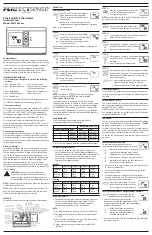
Mount the T8775A,C wallplate, with the screws 
provided. See Fig. 1.

Fig. 1. Mounting wallplate to wall.

M19499

WALL ANCHORS (2)

WIRING HOLE

WALL PLATE

1 INCH SCREW (2)

1  WHEN USING WALL ANCHORS, DRILL 3/16 IN. HOLES
 

FOR DRYWALL, 7/32 IN. HOLES FOR PLASTER.

1

Содержание Digital Round T8775A

Страница 1: ...the ratings given in the instructions and on the product to make sure the product is suitable for your application 3 Installer must be a trained experienced ser vice technician 4 After installation is complete check out prod uct operation as provided in these instruc tions CAUTION Electrical Shock or Equipment Damage Hazard Can shock individuals or short equipment circuitry Disconnect power supply...

Страница 2: ...TION AS REQUIRED W R HEATING RELAY OR VALVE COIL M19513 1 1 M19514 HEATING RELAY OR VALVE COIL FAN RELAY 1 POWER SUPPLY PROVIDE DISCONNECT MEANS AND OVERLOAD PROTECTION AS REQUIRED 2 FACTORY INSTALLED JUMPER 1 2 W R Rc B O Y G 1 HEATING RELAY OR VALVE COIL COMPRESSOR CONTACTOR FAN RELAY M19515 1 POWER SUPPLY PROVIDE DISCONNECT MEANS AND OVERLOAD PROTECTION AS REQUIRED 2 FACTORY INSTALLED JUMPER 2 ...

Страница 3: ... See Table 1 Table 1 Heat Cycle Rate Fahrenheit Celsius Indication Use DIP switch 3 to set the desired temperature indication See Table 2 Table 2 Temperature Indication Mounting Thermostat to Wallplate Fig 9 Mounting thermostat to wallplate OPERATION Setting SYSTEM and FAN Switches T8775C only System and fan settings are controlled manually by using the switches located at the top of the thermosta...

Страница 4: ...ooling T8775C only CAUTION Low Temperature Hazard Operating at too low of an outdoor temperature may cause compressor damage Do not operate cooling if outdoor temperature is below 50 F 10 C Refer to manufacturer s recommendations NOTE If a call for cooling is made before the com pressor has been off for five minutes or if a power interruption occurs while the com pressor is running the thermostat ...

Страница 5: ...idades locales de manejo de residuos para recibir instrucciones relacionadas con el reciclaje y disposición adecuados de un control usado que contenga mercurio en un tubo sellado INSTALACIÓN Al instalar este producto 1 Lea con cuidado estas instrucciones De no seguirlas se podría dañar el producto o provocar una situación peligrosa 2 Verifique los valores nominales de las instrucciones y del produ...

Страница 6: ...eado debe cumplir con los códigos y reglamentos eléctricos locales Desconecte la fuente de alimentación para prevenir una descarga eléctrica o daños al equipo Consulte las Figuras 2 a 6 para ver las conexiones de cableado típicas Figura 2 Conexión típica del termostato T8775A en un sistema exclusivamente de calefacción Figura 3 Conexión típica del termostato T8775C en un sistema exclusivamente de ...

Страница 7: ...FUENTE DE ALIMENTACIÓN INCLUYA MEDIOS DE DESCONEXIÓN Y PROTECCIÓN CONTRA SOBRECARGAS SEGÚN SE REQUIERA 1 2 1 CONTACTOR DEL COMPRESOR MS19517 1 FUENTE DE ALIMENTACIÓN INCLUYA MEDIOS DE DESCONEXIÓN Y PROTECCIÓN CONTRA SOBRECARGAS SEGÚN SE REQUIERA QUITE EL PUENTE INSTALADO EN FÁBRICA ENTRE R Y RC 2 W R Rc B Y G RELEVADOR DEL VENTILADOR RELEVADOR DE CALEFACCIÓN O BOBINA DE VÁLVULA 1 4 VÁLVULA DE CONM...

Страница 8: ...os interruptores DIP 1 y 2 para ajustar la razón del ciclo de calor Vea la Tabla 1 Tabla 1 Razón del ciclo de calor Indicación de grados Fahrenheit Celsius Utilice el interruptor DIP 3 para ajustar la indicación de la temperatura deseada Vea la Tabla 2 Tabla 2 Indicación de la temperatura Montaje del termostato a la placa de fijación Figura 9 Montaje del termostato a la placa de fijación MS19497 I...

Страница 9: ...de 45 F a 99 F 7 C a 37 C para el enfriamiento Calefacción 1 Deslice el interruptor SYSTEM a la posición de calefacción y el interruptor FAN a la posición Auto sólo el T8775C 2 Aumente el punto de referencia de temperatura varios grados por arriba de la temperatura ambiente 3 Debe aparecer una flama en la pantalla y debe encenderse la calefacción 4 Baje el punto de referencia de temperatura debajo...

Страница 10: ...nutos para proteger al compresor El símbolo de copo de nieve va a parpadear durante este retraso 1 Deslice el interruptor SYSTEM a la posición de enfriamiento y el interruptor FAN a la posición Auto 2 Baje el punto de referencia de temperatura varios grados por debajo de la temperatura ambiente 3 Después de aproximadamente cinco minutos el termostato mostrará el símbolo del copo de nieve sólido y ...

Страница 11: ...7XX XXXX X 7 69 1677ES 1 ...

Страница 12: ...ev 6 04 www honeywell com yourhome Soluciones de automatización y control Honeywell International Inc Honeywell Limited Honeywell Limitée 1985 Douglas Drive North 35 Dynamic Drive Golden Valley MN 55422 Scarborough Ontario M1V 4Z9 ...

Отзывы: