background image

 BULLETIN 1166 

9/4/2015 


Page 1 of 20 

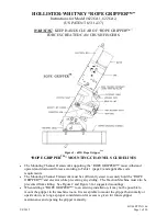
HOLLISTER-WHITNEY “ROPE GRIPPER™” 

Instructions for Model #622GA1, 622GA2,  

(US PATENT 8,511,437) 


WARNING:

 KEEP HANDS CLEAR OF “ROPE GRIPPER™”.   

FORCES CREATED CAN CRUSH FINGERS. 


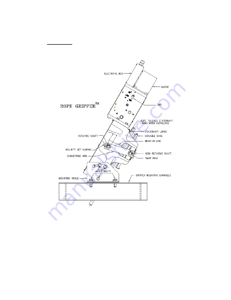
Figure 1 - 622G Rope Gripper

TM


“ROPE GRIPPER

TM

” MOUNTING CHANNELS GUIDELINES 


The Mounting Channel Framework supporting the “ROPE GRIPPER™” must withstand 
upward and downward forces according to Table 1 (page 4) and applicable code 
requirements.   


The Mounting Channel Framework must be sufficiently sized to securely hold the “ROPE 
GRIPPER™” and elevator while preventing any sliding.  The Traction Machine must also be 
prevented from sliding.  See Figure 2 and Figure 3 for suggested mountings. 


When adding a “ROPE GRIPPER™” to an existing installation, it may not be possible to 
mount the gripper in the machine room. It is acceptable to mount the gripper horizontally or 
upside down, as long as proper consideration for access is given for future gripper 
maintenance and opening the gripper manually.


Summary of Contents for ROPE GRIPPER 622GA1

Page 1: ...able 1 page 4 and applicable code requirements The Mounting Channel Framework must be sufficiently sized to securely hold the ROPE GRIPPER and elevator while preventing any sliding The Traction Machine must also be prevented from sliding See Figure 2 and Figure 3 for suggested mountings When adding a ROPE GRIPPER to an existing installation it may not be possible to mount the gripper in the machin...

Page 2: ...BULLETIN 1166 9 4 2015 Page 2 of 20 Typical Mounting Arrangement for Overhead Machines New Installations Figure 2 622G Rope GripperTM Installed at an Angle Figure 3 622G Rope GripperTM Installed Upright ...

Page 3: ...LETIN 1166 9 4 2015 Page 3 of 20 Typical Mounting Arrangement for Overhead Machines Existing Installations Figure 4 622G Rope GripperTM Installed at an Angle Figure 5 622G Rope GripperTM Installed Upright ...

Page 4: ...orqued correctly See Table 1 Double check rope alignment Make sure the ropes touch the stationary shoe lining evenly Reinstall movable shoe assembly Reinstall connecting arms with chamfered edges facing the inside of the gripper and secure the four retaining rings Remove Electrical Box cover Install proper fitting with power and control wiring See Diagram 4 or 5 on page 14 or 15 Connect terminals ...

Page 5: ...de wall of the gripper to aid in the Wear In process Note that at this point in the procedure this line is well above the Connecting Arm and will be met or covered by the Connecting Arm during the Wear In process see Figure 1 for locations of Connecting Arm and Wear In Line Make sure OMS lever is on Auto Reset Run the car at the slow or inspect speed Keeping hands clear of all equipment use cautio...

Page 6: ...THE JUMPER FROM RG5 TO RG7 Failure to remove the jumper will cause unsafe conditions If the lining wear in is not completed after the grooves in the linings have reached approximately 1 16 1 5 mm deep spacer shims see Figure 8 below can be moved from between the shaft support blocks and moveable shoe to the outside of the support block to allow the rotating shaft to just turn the corner and move u...

Page 7: ...ve wear switch see Figure 6 on page 5 will open and the ROPE GRIPPER will not automatically reopen reload In this case you must inspect the linings and decide whether the spacer shims should be adjusted or the linings should be replaced This will depend on whether the grooves in the linings are more or less than 3 16 4 75mm deep To inspect linings for wear first reopen the ROPE GRIPPER using Metho...

Page 8: ... Use wrench to open gripper only as far as is necessary to install security set screws Opening gripper further with socket wrench will damage gripper o Once in the open position insert the security set screws so they touch the rotating shaft Note Before changing shoes or spacers install security set screws to prevent unintended ROPE GRIPPER activation leading to severe personal injury and or damag...

Page 9: ...s to between the shaft support blocks and moveable shoe Loosen the bolts that hold the blocks to the movable shoe move the spacer shims to under the blocks and reinstall and tighten bolts Addition of shims between the block and the shoe will lower the position of the rotating shaft toward the bottom end of the cam when clamping When adjustment replacement is complete turn OMS lever to Auto Reset a...

Page 10: ...ed that the reset control acts as a constant pressure switch for the first ten seconds before latching in the run condition after ten seconds It is suggested that if the elevator controller has a monitor function for the machine brake that the rope gripper be activated immediately on sensing a stuck brake condition rather than waiting for unintended motion to occur The suggested circuits shown in ...

Page 11: ...Page 11 of 20 Diagram 1 See Diagram 4 or 5 for Rope Gripper circuits Diagram 2 Diagram 3 NOTE If force guided relays are used for RG1 RG2 DZ1 and DZ2 use this diagram 622GA2 622GA1 622GA2 3 A for 622GA2 622GA1 Omit for 622GA1 ...

Page 12: ...t is accomplished by resetting the Governor overspeed switch and the elevator control circuits Refer to and follow the controller manufacturer s instructions for ROPE GRIPPER reset IMPORTANT The code requires that the ROPE GRIPPER be manually reset if it is triggered by fault It is intended that a qualified technician inspect for and correct any malfunction before the car is placed back into servi...

Page 13: ...activate the ROPE GRIPPER causing it to clamp the ropes and stop the car When the ROPE GRIPPER is activated the ELEVATOR CAN RUN contacts will open and signal the controls to interrupt power to the driving motor and machine brake 2 ASCENDING CAR OVERSPEED TEST With an empty car overspeed the car in the UP direction while keeping the machine brake open The Governor overspeed switch will activate th...

Page 14: ...BULLETIN 1166 9 4 2015 Page 14 of 20 Diagram 4 622G Rope GripperTM Wiring Schematic 110V ...

Page 15: ...BULLETIN 1166 9 4 2015 Page 15 of 20 Diagram 5 622G Rope GripperTM Wiring Schematic 220V ...

Page 16: ...y be applied to these areas if it is found to be lacking WIRE ROPE LUBRICATION Proper lubrication of the ropes will not affect Rope Gripper operation Use a high friction lubricant such as Nylube Cable Care 65 or American Oil Vitalife 600 Figure 11 Overall Dimensions of 622G Rope GripperTM For further technical assistance please contact HOLLISTER WHITNEY directly Hollister Whitney Elevator Corp 1 H...

Page 17: ...ASE CONNECTING ARM EXTERNAL RETAINING CLIP 20MM 622 020 M 1 CONNECTING ARM ASSEMBLY 620 208 01 1 CAPACITOR FOR 220V AC 50 60 Hz MOTOR SCREWS 620 208 02 1 CAPACITOR FOR 110V AC 50 60 Hz MOTOR SCREWS 622 301 1 M 1 MOTOR CLUTCH SUB ASSEMBLY 220V 620 301 2 M 1 MOTOR CLUTCH SUB ASSEMBLY 110V 622 303 M 1 CONTACT FORK ASSEMBLY ...

Page 18: ...escription Picture 622 304 M 1 DELAY CIRCUIT ASSEMBLY HARDWARE 622 327 M 1 RACK CONNECTION PIN AND RETAINING CLIP 8MM 622 326 M 1 MANUAL RESET SPRING PLUNGER M6X1 0 STEEL 622 306 M 1 CONTACT BLOCK ASSEMBLY 622 328 M 1 MICROSWITCHES OPERATING MODE SELECTOR ...

Page 19: ...Number QTY Description Picture 622 307 M 1 MICROSWITCH ELEVATOR CAN RUN LOCKOUT 622 308 M 1 MICROSWITCH READY EXCESSIVE WEAR 620 242 2 GEAR BOX WIRE CLIPS 622 311 M 1 GEAR BOX COVER SCREWS 622 309 M 1 ELECTRICAL BOX COVER WIRING DIAGRAM SCREWS ...

Page 20: ... 1 CABLE GLAND B TYPE SEAL HOLE SHORT THREAD 620 204 5 RUBBER GROMMET 622 310 1 M 1 BASE ASSEMBLY COVER SCREWS 220V 622 310 2 M 1 BASE ASSEMBLY COVER SCREWS 110V 622 329 M 1 BRAKE PAD LINING ASSEMBLY SCREWS 622 330 M 4 SPACERS 622 LINING SCREWS 620 121 M 2 HALF DOG SET SCREW M6 X 35 ...

Reviews: