Hitachi WH 14DSL, Technical Data And Service Manual
The Hitachi WH 14DSL is a high-quality power tool designed for efficient handling and improved productivity. Get the most out of this impressive tool by referring to its comprehensive Handling Instructions Manual. Download this manual for free from our website and unlock the full potential of the Hitachi WH 14DSL.
Share
Download


Reviews:
No comments
Related manuals for WH 14DSL

PIW1050-C
Brand: P.I.T. Pages: 19

310452 1904
Brand: Parkside Pages: 89

ARI1278-3
Brand: ACDelco Pages: 32

NJ.1400F 826558
Brand: Facom Pages: 48

94803
Brand: Central Pneumatic Pages: 8
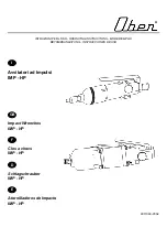
8302512
Brand: Ober Pages: 28

BTD141
Brand: Makita Pages: 2

WX252
Brand: Worx Pages: 92

2051474724
Brand: Desoutter Pages: 60

280016
Brand: Ribitech Pages: 32

PJID143
Brand: Max Pages: 20

IW24L00
Brand: GreenWorks Pages: 28

ID24B00
Brand: GreenWorks Pages: 56

ISD401
Brand: GreenWorks Pages: 112

PSBIW25
Brand: Ryobi Pages: 24


