background image

HITACHI

   Printer

Technical Manual

INK JET PRINTER FOR INDUSTRIAL MARKING 

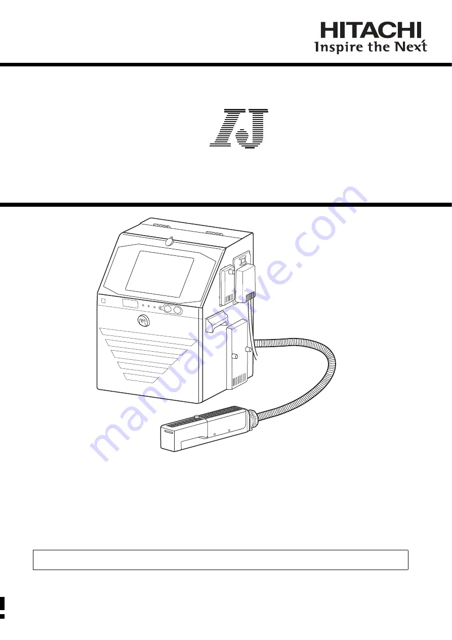
Model UX Twin-Nozzle

Thank you for purchasing the Hitachi IJ Printer Model UX Twin Nozzle.
This printer employs a noncontact, ink-jet method to print onto a print target.
This instruction manual describes the basic operating procedures, maintenance procedures, and other detailed 
handling procedures of the Hitachi IJ Printer Model UX Twin Nozzle.
If the printer is improperly handled or maintained, it may not operate smoothly and may become defective or 
cause an accident.  It is therefore essential that you read this manual to gain a complete understanding of the 
printer and use it correctly.
After thoroughly reading the manual, properly store it for future reference.

IF you changed the language of screen by mistake,see "7.8 Selecting Languages" in the Instruction Manual.

Summary of Contents for UX Twin-Nozzle

Page 1: ...rocedures and other detailed handling procedures of the Hitachi IJ Printer Model UX Twin Nozzle If the printer is improperly handled or maintained it may not operate smoothly and may become defective or cause an accident It is therefore essential that you read this manual to gain a complete understanding of the printer and use it correctly After thoroughly reading the manual properly store it for ...

Page 2: ... warning against performing an incorrect handling procedure is ignored CAUTION CAUTION is used to indicate the presence of a hazard which may cause personal injury or property damage if the warning against performing an incorrect handling procedure is ignored Pictograph Examples The symbols are used to indicate precautions including those related to potential warnings to be observed Detailed infor...

Page 3: ...ter in order to prevent it from filling with organic solvent vapor Secure adequate space for the ink makeup handling area and printer installation site At least 400 m must be provided per print head Ensure that adequate ventilation is provided 1 2 Installation Environment of Printer 3 CAUTION If extraneous noise enters the printer it may malfunction or break down For maximum noise immunity observe...

Page 4: ...section of the printer and to make a separate ground connection for the printer If you wish to receive ink particles in a beaker for a printing test for example use an electrically conductive beaker and connect the beaker securely to the ground Do not let the tip of the printing head enter the beaker Ink particles used for printing are electrically charged An ungrounded beaker has a gradually risi...

Page 5: ...remain inside Should you find a leak of ink or makeup inside the printer while the printer is running or being maintained wipe it off promptly with wiping paper or something similar Then with the maintenance cover open stop the printer power it down and repair the leak Continuing operation with a leak of ink or makeup will cause an anomaly resulting in abnormal printing Ink and makeup are flammabl...

Page 6: ...printer is operating do not look into the ink ejection hole in the end of the print head Ink or makeup may enter your eyes or mouth or soil your hands or clothing If any ink or makeup enters your eyes or mouth immediately flush with warm or cold water and consult a physician When ejecting the ink do it after confirming that there is no one in the ejection direction Operate with the end of the prin...

Page 7: ...armful interference and 2 this device must accept any interference received including interference that may cause undesired operation This equipment has been tested and found to comply with the limits for a Class A digital device pursuant to part 15 of the FCC Rules These limits are designed to provide reasonable protection against harmful interference when the equipment is operated in a commercia...

Page 8: ... ink for details AVERTISSEMENT Tenir hors de portée du feu L encre et la composition sont inflammables Tenir la machine hors de portée du feu Nettoyez et séchez immédiatement les projections d encre et de composition Soyez prudent lorsque vous manipulez l encre la composition Le stockage doit respecter les obligations réglementaires locales Lisez attentivement la fiche signalétique de sécurité de ...

Page 9: ...2 Connection to input output I O terminals 4 5 4 3 Input output I O specifications 4 8 4 3 1 Print target detector input 4 9 4 3 2 Product speed matching function using a rotary encoder 4 13 4 3 3 Input function 4 18 4 3 4 Output function 4 22 4 3 5 Product speed matching function without a rotary encoder 4 25 5 COMMUNICATION 5 1 5 1 Overview 5 1 5 2 Setting Communication Environment 5 3 5 2 1 Set...

Page 10: ...es on Print Condition Transmission 5 65 5 9 Communication Buffer 5 66 5 9 1 Overview 5 66 5 9 2 Description of Functions 5 67 5 9 3 External Communications 5 70 5 9 4 Errors 5 71 6 CIRCULATION SYSTEM WORK AND ADJUSTMENT METHOD 6 1 6 1 Circulation control screen operation and contents 6 2 6 1 1 Circulation control screen operaion 6 2 6 1 2 Circulation control contents 6 3 6 2 Removing Inner Cover 6...

Page 11: ...rm Shutdown 6 39 6 15 1 Process prior to long term shutdown 6 40 6 15 2 Startup process after long term shutdown 6 44 7 MAINTENANCE SERVICE 7 1 8 SCHEMATIC DIAGRAMS 8 1 8 1 Outside Dimensions 8 1 8 2 Electrical Connection Diagram 8 3 8 3 Circulation System Diagram 8 4 8 4 Tube Connection 8 5 9 APPENDIX 9 1 Barcode 2 dimensional code 9 1 Setting high speed printing 9 6 Using reverse scan print 9 9 ...

Page 12: ...ee the figure at right 2 The print head needs to be cleaned with the makeup while the printer is operated and stopped daily maintenance Adopt a fixed structure in consideration of print head cover and print head removal 3 Installation must be completed so that no vibration will be applied to the IJ printer main body print head or print head cable If they are vibrated print quality deterioration an...

Page 13: ...int head below the printer main body installation surface ensure that the distance between the end of the print head and the installation surface does not exceed 1 m 2 1 Print head Print head cable Bend R 0 5m 10 When using the printer for upward or lateral printing ensure that the rising print head cable upper end is positioned not more than 0 5 m above the print head 11 If you fixed the print he...

Page 14: ...ls for fixing the print head 15 In the case of carrying the printer proper use the handles in the drawing below Connect a duct to this port 50 mm in diameter Exhaust duct connection port 13 When connecting an exhaust duct to the printer install a damper and adjust the wind velocity at the intake port to 0 3 to 0 5 m s Use an anemometer for verification If the wind velocity is too high the makeup c...

Page 15: ...ive humidity is 85 or higher complete the print head air purge procedure When a water drainage blow sequence is performed before printing When the printer is used in a place where a considerable amount of paper powder or other dust exists When the printing distance is short so that the end of the print head is splashed with ink When you use inks that are indicated on the handling guidance of each ...

Page 16: ...t message Edit message Calendar conditions Substitution rules setting Count conditions Select message Select message Save message Save message Overwrite message Print specifications Print specifications Various print setup Adjust print parameters Print format Print format Adjust inter character space Maintenance Auxiliary functions Manage messages group Create user pattern Calibrate touch screen c...

Page 17: ...s for each user Sets the password Delete the user Create the new user Press Login management of the Environment setup menu The Login management menu is displayed Log in as a user with administrator rights when User conditions setup or Using environment setup are not displayed on Login management menu 1 2 Operation The administrator is logged in Press User conditions setup The User conditions setup...

Page 18: ...Sets function restrictions Displays the kind of administrator rights OK Password setup Modifies the user name Select user5 user5 settings are displayed 3 Select the administrator rights 4 Select access or protect for each function item 5 Press Password setup and set the password 6 Press OK The administrator rights function restrictions user name and password for user user5 are set 7 An error messa...

Page 19: ...iew When Password protection is valid it can be canceled in units of Print item When Administrator logs in Password protection can be canceled 2 Operation The character input is made as follows USE BY 18 07 07 Column 1 Column 2 For user5 whose Administrator rights is Users set Edit message to protect Password protection for Column 2 will be canceled Administrator logs in 1 As described in Section ...

Page 20: ...Password protection Print spec Pint format Twin Back 0 AB N2 Password protection 2018 07 07 12 45 Stop Message name SAMPLE 1 USE BY 18 07 07 USE BY 18 07 07 Makeup Ink Back protect all Twin pro tect access Com 0 Manual HOME Startup 0 AB N2 Press Edit message on Change message screen Edit message screen will be displayed 5 Press Password protection on Edit message screen Password protection screen ...

Page 21: ... Manual HOME Startup 0 AB N2 Apply Press Next item The cursor moves to Column 2 7 Press access Password protection where the cursor is placed will be canceled and the character s shade will disappear The character input will be available on Column 2 8 Press Apply All inputs which are set on Password protection screen will be applied 9 Press HOME It will return to Print description screen 10 Login ...

Page 22: ...ged by login user change function even when the login method is Disable User conditions setup and Using environment setup can be started when the administrator is logged in 2 Operation Log in the administrator Login management menu 2018 07 07 12 45 Stop Login history Select login user Password setup User conditions setup Using environment setup Create new user ID Delete user ID Makeup Ink Manual S...

Page 23: ...rtup OK Cancel When Enable is selected selects the user which logs in when the power is turned on OK Login method Administrator Automatic Deselect Press Using environment setup The Using environment setup screen is displayed 2 Press Login method Enable 3 Select the login method and press OK Sets whether or not to select a user which logs in when power is turned on 4 When the Login method is Enable...

Page 24: ... User who last logged in Switch to User of the smallest number YES YES YES NO NO NO 2 Working conditions The working conditions of this new function are listed in Table1 below Only when all the conditions are met this new function will work No Working conditions 1 Administrator Automatic Deselect is set to Enable 2 One or more than one user are registered as the Login user 3 One of the menus below...

Page 25: ... does not return a user automatically Login management menu 2018 07 07 12 45 Stop Login history Select login user Password setup User conditions setup Using environment setup Create new user ID Delete user ID Makeup Ink Manual Startup HOME Com 0 Back Sets whether or not to select a user which logs in when power is turned on Sets function restrictions for each user Sets the password Delete the user...

Page 26: ... Enable Disable Makeup Ink Manual HOME Startup OK Cancel Com 0 Specifies the login user When Disable is selected the Print description screen is immediately displayed when the power is turned on OK When Enable is selected it does return a user automatically Press Administrator Automatic Deselect Enable 3 Select the Administrator Automatic Deselect and press OK Administrator Automatic Deselect is s...

Page 27: ...n When Human Machine Interface HMI is set to New the general user can have an access only to the following seven screens Seven screens are hereinafter called New HMI screens New HMI screens New icons Print description screen HOME Open screen OPEN Save screen SAVE Adjust print parameters screen ADJUST Edit screen EDIT Operation management screen SETTINGS Select login user screen LOGIN When Human Ma...

Page 28: ... display HMI used by general users can be set to new system screen or conventional screen 5 When Human Machine Interface HMI is set to New the general user cannot change perform maintenance operations such as circulation control In the case of these operations you must login again as the administrator user When Human Machine Interface HMI is set to New the New HMI screens will be displayed at syst...

Page 29: ...t target detector print head stand and IJ printer body from other machinery and equipment conveyor etc Separate the print target detector wiring from other power lines Perform that all electrical wiring connections and grounding comply with applicable cords When erroneous operation was caused by noise etc use a dedicated ground 4 ELECTRIC SIGNAL CONNECTION 1 2 3 4 5 2 Connection to power supply Us...

Page 30: ...sed welding work becomes possible even while the IJ printer is operating Fire is strictly forbidden around the IJ printer The ink and makeup are both flammable Welding sparks may cause ignition or a fire Take measures so that sparks do not enter the surrounding area whether or not the IJ printer is operating and ventilate sufficiently Just in case ensure safety by installing a powder type fire ext...

Page 31: ...ernal communications connector inside the IJ printer When performing wiring work always turn off the power During normal use leave the top cover closed CAUTION Use cables with an outside diameter within the range specified above Firmly tighten the lead in port lock nut In addition do not bundle weak electric system and strong electric system cables together inside and outside the IJ printer so tha...

Page 32: ...e seal block Wrap the outside of the cable with seal as shown in the figure Wrap the seal so that there is no gap between it and the cable seal block Reassemble the cable seal block by following the opposite procedure 1 2 3 4 Remove the lock nut Pass the cable through as shown in the figure Tighten the lock nut Tighten the lock nut securely using a tool 1 2 3 Seal Cable Lead in port connection met...

Page 33: ... terminals Overview of Terminals and Connectors The terminal block and connectors for wiring are located behind the electrical access door upper front panel door Usage for the External connection terminal block 1 TB1 Applicable cable size AWG24 to 16 Φ0 5 to 1 3 Wire covering to be stripped 8 to 9 mm Faulty wiring causes the substrate breakdown Before wiring be sure to confirm the terminal signal ...

Page 34: ...1 Signal ground 12 Fault Output 13 Warning Output 14 Deflection voltage ON OFF signal Input NPN PNP can be selected by SW2 15 Reciprocative print signal Input 16 Run signal Input 17 Reset signal Input 18 Stop signal Input 19 Print in progress Print complete Output Print in progress Print complete can be selected with screen operation NPN PNP can be selected by SW2 20 Online output Output 21 Univer...

Page 35: ...Use either NPN or PNP interface for input output signals 4 to 5 and 14 to 23 Do not use a combination of the interfaces for these input output signals Interfaces can be combined for units of print material sensor signals 1 to 3 encoder signals 6 to 9 input output signals 4 to 5 14 to 18 and status output signals 19 to 22 For example PNP interface can be used for print target detector and NPN inter...

Page 36: ...e Vout 24 V 3 Totem pole ON state I in at24V 20mA max OFF state V in 1V max 3 5 Run 2 Functionally the same as the RUN key on the operator panel Performs processing from ink injection to ready to print ON state I out 6 mA max OFF state Vout 24 V 3 ON state I in at24V 6 mA max OFF state V in 1V max 3 6 Reset Functionally the same as the Reset key and the Message Delete key on the Error Message wind...

Page 37: ...and Print completed one must be selected from a screen Print target detector TB1 DC24V Signal GND Power Signal GND 1 2 NC 4 3 SW1 3 ON SW1 5 ON SW1 6 OFF ON 1 SW1 setting ON OFF 2 3 4 5 6 7 8 Print target detector Signal Power Signal SW1 3 OFF SW1 5 ON SW1 6 ON SW1 setting TB1 GND NC GND 1 2 DC24V 4 3 ON 1 ON OFF 2 3 4 5 6 7 8 4 3 1 Print target detector input This function inputs the IJ printer p...

Page 38: ...rint target detector IJ printer 1 2 3 IL 2 Print target detector specifications a When NPN interface is used Internal circuit diagram When the IJ printer input circuit is a current drive load for the print target detector output circuit and output transistor Tr of the print target detector is ON it becomes the print start signal input Use an output transistor Tr which satisfies the following speci...

Page 39: ...circuit diagram b Addition of external noise filter In case that the built in noise filter cannot eliminate the noise add the following additional CR filter outside of IJ Printer If R1 1kohm 0 5W and C1 1micro farad 25V the CR time constant 1ms If R1 1kohm 0 5W and C1 1micro farad 25V the CR time constant 1ms The filter could eliminate a several hundred micro seconds of noise If you need to elimin...

Page 40: ...tion frequency 68 9 Model UX with 65µm nozzle and 1067K ink Refer to Handling guidance of each ink manual to check the supported excitation frequency Note 1 Time for repeated printing of fixed characters When using the communications function or 2 dimensional bar code function it will be longer than the time calculated from this formula When the speed is followed up the number of encoder pulses sh...

Page 41: ...r Ordinarily a rotary encoder is used for this purpose The IJ printer can print each vertical line of the printed message in synchronization with the pulses from the rotary encoder 4 3 2 1 Rotary encoder specifications wiring and switch setting 1 The specifications of the connectable rotary encoders are Output waveform Square wave duty 30 to 70 Output withstand voltage 24VDC or greater Load curren...

Page 42: ...e div factor at the Print specifications screen See 4 14 Set the print specifications in the Instruction Manual Set Product speed matching to 1 Enable Set Pulse rate div factor as required This function lowers makes the period longer the frequency of the input pulses inside the IJ printer The divided pulses become the pulses used in printing Description of pulse division function The rotary encode...

Page 43: ...eter of the type used at d 1 60 Nozzle diameter d 65μm 0 33 3 Next use Eq 3 to check if the maximum print scan frequency found from Eq 2 can be matched at IJ printer set print speed When the result of Eq 3 is smaller than the maximum print scan frequency Eq 2 product speed matching is not performed normally and the character width becomes large Max number of print scans kHz Highest conveyor speed ...

Page 44: ...hing function is used is determined by the amount of movement of the product per encoder pulse Several examples are introduced below Example 1 Calculate the resolution of the rotary encoder when the rotary encoder is connected directly to the conveyor shaft Calculation conditions Dot font 5 7 dots horizontal direction 5 vertical direction 7 Inter character space 1 dot 1 scan Inter character interv...

Page 45: ...solution from rotary encoder 188 4mm rev 3 33 scans mm 628PPR Diameter ratio RT of pulley RT Diameter of pulley B diameter of pulley A 1 000PPR 628PPR Approx 1 6 1 1 2 3 4 Pulley Diameter Encoder Conveyer Example 3 Calculate the necessary rotary encoder resolution when a pulley is installed to the shaft of the rotary encoder and this pulley is connected to the conveyor Calculation conditions Dot f...

Page 46: ...nputting print stop remote operation Startup Shutdown Reset Deflection voltage control and reciprocative print switching to pins 4 5 and 14 to 18 of TB1 by switch or contact signal from the outside Internal circuit diagram a NPN interface input no voltage input No contact signal transistor Withstand voltage 30VDC or greater Maximum drive current 6mA or greater Residual voltage 2V or less Leakage c...

Page 47: ...al after signal changeover Print stop signal ON OFF 50ms or greater 0ms or greater OFF OFF Printing ON ON 50ms or greater 20ms or greater 50ms or greater Printing No printing Print target detector Printing in progress signal Printing operation 4 3 3 1 Print stop signal input Function This function prevents printing from the outside Note that the Ready to print output signal does not change even if...

Page 48: ...llowing cases When a confirmation window is open When the Circulation control screen is opened by maintenance function When the Touch screen coordinate correction screen is opened by auxiliary function 1 2 3 i ii iii a 2 Deflection voltage control When Deflection voltage control is input continuously a certain OFF period is necessary When t2 is 10ms or less OFF is not detected and the signal is no...

Page 49: ... state after the Shutdown signal is turned ON It takes about 3 minutes for the IJ printer to enter the Stop state after the Shutdown signal is turned ON The time until the state changes after the Shutdown signal is input t6 within 100ms 1 2 3 1 2 Notes 1 For key input input must be confirmed but when an external signal is input processing is performed in accordance with the signal instructions Esp...

Page 50: ...e logic is transistor ON at operation ON The voltage and current used by the external equipment must satisfy the following specifications Operation is not guaranteed and the board may be damaged if the specifications are not satisfied IL 20mA VCE TYP0 6V MAX2V Vd DC30V Wiring precautions When the load is a relay solenoid or other inductive load connect a diode to prevent generation of a counter el...

Page 51: ...progress and Print complete switching Switching of the Print in progress and Print complete signals is set at the User environment setup screen See 6 1 Set the user environment in the Instruction Manual b Signal timing 4 3 4 2 Online output signal NPN PNP interface output TB1 20 Function This function outputs a signal to the outside when the IJ printer is online 4 3 4 3 Ready output NPN interface ...

Page 52: ...rinter by serial communication of RS 232C Pin No Name Input Output Remarks 1 NC 2 RD Input 3 SD Output 4 DTR Connect with DSR by IJ printer side 5 SG 6 DSR Connect with DTR by IJ printer side 7 RTS Connect with CTS by IJ printer side 8 CTS Connects with RTS by IJ printer side 9 NC Turn OFF SW1 bit7 on EZJ 127 board Do not bundle it together with heavy current signals inside and outside the equipme...

Page 53: ...rinter setup Configure the setting for Product speed matching Print target width and Actual print width on Print Specifications screen See 4 14 Set the print specifications in the Instruction Manual Set Auto for Product speed matching Enter Print Target width and Actual Print width in mm The value for Actual Print width must be smaller than Print Target width Enable the Speed compensation as requi...

Page 54: ...printer recalls print data designated by a message number and makes preparations for making prints 3 Print data registration transmission Transmits Print data s message number and message name from external unit to the IJ printer The IJ printer provides a message name and registers data currently being printed as print data of registration No 4 Print condition transmission The external device tran...

Page 55: ...o the IJ printer The first print item will be left 12 Count Reset Transmission This function will change the count value to the preset value reset value All count blocks which have the preset Reset value will be reset to Reset value 13 Communication buffer The print contents received through print content transmission will not be reflected in printing immediately but will be temporarily held in bu...

Page 56: ... the outside The following settings are available Data length 7 or 8 bits Parity bit none odd or even Stop bits 1 bit or 2 bits Data length 8 bit Parity bit none Stop bits 1 bit Number of comm bytes Sets the number of character code bytes for communication with the outside A setting of 1 byte or 2 bytes can be selected 1 byte BCC code handling Setup can be performed so that no communication error ...

Page 57: ...t Dsp Comm env setup 2018 07 07 12 45 Stop Buffer function Buffer repeat count Empty Buffer Fault Timing of Fault Data Number at Fault 0 0 9 1 9999 Disable Enable 0001 Setting of communication buffer Refer to 5 9 Communication buffer Disable Enable Print Start Print Complete Makeup Ink Com 0 Manual HOME Startup Back Prev Dsp Next Dsp Comm env setup 2018 07 07 12 45 Stop LAN communication TUP I LAN...

Page 58: ...odd 1 E 1 8 None 2 F default 1 8 None 1 G 1 8 1 even 1 H 1 8 1 odd 1 I 1 8 1 even 2 J 1 8 1 odd 2 Selecting a data length of 7 bits allows you to transmit alphanumerical characters and symbols but inhibits you from transmitting punctuation characters and using 2 byte codes to send dedicated characters and user pattern characters 8 Bit configuration Formats A and B Start b0 b1 b2 b3 b4 b5 b6 Parity...

Page 59: ...ode transmission from the external decice 7 The printings print specifications print format and user pattern data can be consecutively transmitted in the following order in a single session Print format Print specifications Printings 2 1 3 Example Print format Print format Print format Print specification Print specification Print content The user pattern can be positioned anywhere within the abov...

Page 60: ...to be designated by specifying the item numbers The item numbers need not be sorted Print items not transmitted are not changed When the number of the print items and the print items are transmitted at a item by Number of the print items specifying transmission the print items beyond the number of the print items will be deleted Number of the print items specifying transmission shall NOT be made w...

Page 61: ...73 74 75 76 77 78 79 80 Code 77H 78H 79H 7AH 7BH 7CH 7DH 7EH 7FH 80H Item number 81 82 83 84 85 86 87 88 89 90 Code 81H 82H 83H 84H 85H 86H 87H 88H 89H 8AH Item number 91 92 93 94 95 96 97 98 99 100 Code 8BH 8CH 8DH 8EH 8FH 90H 91H 92H 93H 94H The order of print items is indicated below 3 column example Circled number Item number 5 3 2 3 Printings An array of character codes The coding system vari...

Page 62: ...mber of communication bytes 2 byte mode ASCII ASCII High order byte Low order byte High order byte Low order byte ASCII 5 3 2 5 Example of print contents transmission 1 Example when No of communication bytes 1 byte mode 02H 10H 31H 41H 42H 43H 10H 32H 0FH F2H 52H F2H 52H 0EH 03H STX DLE 1 A B C DLE 2 SI Calendar Calendar SO ETX Print item 2 2 Example when No of communication bytes 2 byte mode 02H ...

Page 63: ...sed by a combination of three ASCII codes 5 3 3 3 Example of print contents transmission 1 Example of specifying 4 digit print data registration No 02H 1FH 20H 31H 30H 30H 31H 32H 03H STX ESC2 1 0 0 1 2 ETX Transmission results Calls print data of print data message number 12 ESC Header 56H 100s place 10s place Units place Print data message number 001 to 999 ESC Header 26H 10s place Units place P...

Page 64: ...nits place Print data message number 0001 to 2000 ESC2 Header 21H Classification 32H Message name 1 to 12 digits Message name ASCII code 20H to 5FH 61H to 7AH ESC Header 55H 100s place 10s place Units place Print data message number 001 to 999 ESC Header 25H 10s place Units place Print message number 01 to 99 ESC Header 55H 100s place 10s place Units place ESC Header 86H Message name 1 to 12 digut...

Page 65: ...name ABC is already registered on No 1 Register on No 2 using identical message name Message name of No 1 ABC Message name of No 2 ABC AA 4 Characters available for message name Characters used for setting the message name transmission are different from characters used in manual input on registration screen Function Alphameric character Symbols Accent character Arabic character Manual input Avail...

Page 66: ...No Print format text ESC2 Header 24H Item No Print format text Item No specified 1 to 100 Existing machine message Existing machine message can also be used Print format text If item No is not specified it is set for all items To transmit print format and print specs consecutively transmit in the order of print format and print specs If transmitted the other way round an error will occur 2 1 Print...

Page 67: ...e Prefix code Bar code EAN 13 ESC2 Header 23H Classification 35H Tens position Units position Prefix code 00 to 99 Two or more print format items can be consecutively transmitted in a single chain Inter character space 0 to 28 Character size 30H to 3CH Bar code type 30H not used 31H code 39 32H ITF 33H NW 7 34H EAN 13 35H DM8 32 36H DM16 16 37H DM16 36 38H DM16 48 39H DM18 18 3AH DM20 20 3BH DM22 ...

Page 68: ... Code set B 1 Code set C ESC Header 28H Increased width Increased width Increased width 1 to 9 5 Print specifications Character height ESC2 Header 25H Classification 31H 10s place Units place Character height 00 to 99 Ink drop use percentage ESC2 Header 25H Classification 32H 10s place Units place Ink drop use percentage 01 to 16 High speed printing ESC2 Header 25H Classification 33H Mode Characte...

Page 69: ...nt start delay reverse 0000 to 9999 Product speed matching ESC2 Header 25H Classification 38H Character orientation Product speed matching 0 Time based 1 Encoder based 2 Auto encoder based Pulse rate division Factor ESC2 Header 25H Classification 39H 100s place 10s place Units place Pulse rate division Factor 001 to 999 Repeat count ESC2 Header 25H Classification 3DH 1000s place 100s place 10s pla...

Page 70: ...000s place 100s place 10s place Units place Value 0000 to 9999 Two or more print specification items can be consecutively transmitted in a single chain Ink drop charge rule ESC2 Header 25H Classification 42H Charge rule Charge rule 31H Standard 32H Mixed single scan and interlaced 33H Dot mixed Leading character width control 0 Disable 1 Enable Leading character width control width ESC2 Header 25H...

Page 71: ...verse 0000 to 9999 ESC Header 37H 100s place 10s place Units place Target sensor timer Target sensor timer 000 to 999 ESC Header 38H 1000s place 100s place 10s place Units place Target sensor filter Target sensor filter 0000 to 9999 ESC Header 39H Division Division 1 time setup 2 until end of print High speed printing ESC Header 3AH Mode Mode 0 HM 1 NM 2 QM ESC Header 3CH 100s place 10s place Unit...

Page 72: ...ame chain as the one line setup data If you do not transmit an line spacing setting of 0 a communication error occurs Ensure that the same line spacing setting is selected for print items belonging to the same column In other words when you transmit a new line spacing setting for a print item in a certain column you must consecutively transmit the same setting to the other print items in the same ...

Page 73: ...r Code128 2 byte code of 81A6 indicated as on print layout screen 5 3 5 3 Caution for format type Free layout When the format setup is Free layout and if Line count print format uniformity or Line count and line spacing or High speed printing or Ink drop charge rule is transmitted a communication error will occur 5 3 5 4 Example of print conditions transmission 1 Example where print item is not sp...

Page 74: ...rror will occur 5 3 6 2 Text 1 Specify Horizontal Vertical coordinate and move Specify the bottom left coordinate and the print item will be moved Horizontal and Vertical coordinate ESC2 Header 24H Classification 31H Item number 10000s place 1000s place 100s place 10s place Unit place Contd Item number 1 to 100 Horizontal X coordinate 0 to 31998 10s place Unit place Vertical Y coordinate 0 to 29 H...

Page 75: ...ve input either 00000 or 00000 In case there will be NO vertical move input either 00 or 00 Horizontal move ESC2 Header 24H Classification 42H Item number Item number 1 to 100 Contd Horizontal sign Input either one of the two 2BH plus 2DH minus Horizontal sign 10000s place 1000s place 100s place 10s place Unit place Horizontal X direction 31998 to 31998 Either plus or minus sign to be input for Ho...

Page 76: ...orizontal X coordinate will be set to 120 and Vertical Y coordinate to 25 Vertical Y coordinate 02H 1FH 24H 32H 31H 31H 32H 33H 34H 35H 03H STX ESC2 2 1 1 2 3 4 5 ETX Horizontal X coordinate Header classification Transmission result Print item 1 Horizontal X coordinate will be set to 12345 02H 1FH 24H 33H 94H 30H 30H 03H STX ESC2 3 100 0 0 ETX Item No Vertical Y coordinate Header classification Tr...

Page 77: ...2H 33H 34H 35H 2DH 30H 30H 03H STX ESC2 A 2 1 2 3 4 5 0 0 ETX Item No Horizontal X direction Header classification Transmission result Move print item 2 rightward by 12345 Vertical Y direction 02H 1FH 24H 41H 62H 2BH 30H 30H 30H 30H 30H 2DH 31H 30H 03H STX ESC2 A 50 0 0 0 0 0 1 0 ETX Item No Horizontal X direction Header classification Transmission result Move print item 50 downward by 10 Vertical...

Page 78: ... No Type Mode ESC2 Header 76H Item No Type 1000s place 100s place 10s place Units place Offset Offset Zero suppression ESC2 Header 77H Item No Type Disable or Enable Disable or Enable 0 Disable Calendar block No 1 to 8 Type 30H Year 31H Month 32H Day 33H Hour 34H Minute Calendar block No 1 to 8 Type 30H Year 31H Month 32H Day 33H Hour 34H Minute 35H Weeks 36H Day of week Mode 30H Disable 31H Zero ...

Page 79: ...pdate setting range Unit 000001 to 999999 36H Increment setting range 01 to 99 37H Direction 0 up 1 down 38H Jump from Character code 39H Jump to Character code 3AH Reset Character code 3BH Reset signal option 0 signal 1 1 signal 2 3EH External signal count option 0 Disable 1 Enable Character code of setting value Mode Alphanumeric User pattern 1 byte mode ASCII ASCII 2 byte mode ASCII 2 byte code...

Page 80: ...etting range Set item Update setting range In progress 000000 to 999998 Unit 000001 to 999999 ESC Header 82H Item No Type 0 1 3 Direction External signal count Reset signal Direction 0 up 1 down External signal count 0 Disable 1 Enable Reset signa 0 Signal1 1 Signal2 Code of type Direction External signal count Reset signal ASCII 30 31 32 ASCII is hexadecimal number ESC Header 83H Item No Type 10s...

Page 81: ... purposes ESC2 Header 32H Classification High order byte Low order byte Pattern data array Character size Character code ESC2 Header 20H Character size Character code Pattern data array When the number of communication bytes is set to 1 for communication environment setup purposes When the number of communication bytes is set to 2 for communication environment setup purposes ESC2 Header 20H Charac...

Page 82: ...H 27 20 First byte Second byte Third byte byte 4 byte 5 byte 6 byte 7 byte 8 For pattern data composition purposes the data is arranged in successive order beginning from the bottom left from bottom to top and from left to right b Pattern data example For a character size of 5 5 Composition order 1 2 3 4 5 6 7 8 Pattern data 07H 0AH 12H 0AH 07H 00H 00H 00H ...

Page 83: ...byte codes when the number of communication bytes is 2 User pattern character 00 F140 high order byte F1 low order byte 40 See 5 4 1 Code Tables 5 3 8 5 Supplement 1 If the same character code is used to transmit two or more user pattern character data in a single message the last transmitted data takes effect 2 When two or more user pattern characters having differing character sizes or character...

Page 84: ...s displayed while inputting set value In the Communication environment setup screen Off fixed is selected for State at power up item During input of count conditions The confirmation window is open The circulation control screen is opened by the maintenance function The touch screen setup screen is opened by the auxiliary function The communication monitor screen is opened 2 1 3 4 5 6 5 3 9 2 Tran...

Page 85: ... status 2 Operation stop Stops ink ejection and shifts to stop status Same process as with Shutdown button When ink is being ejected standby ready status etc 3 Deflection voltagecontrol ON Turns deflection voltage on Same process as with Ready button in Manual control menu window Standby status 4 Deflection voltagecontrol OFF Turns deflection voltage off Same process as with Standby button in Manu...

Page 86: ... ESC2 Header 2EH Classification 33H 1000s place 100s place 10s place Units place 10s place Units place Year Month Contd 10s place Units place 10s place Units place 10s place Units place 10s place Units place Day Minutes Hour Second Clock system ESC2 Header 2EH Classification 34H Control type 2 Current time output transmission Outputs current time of IJ printer internal calendar ESC2 Header ACK Ext...

Page 87: ...g item Setting contents 1 Current time Current date time displayed across the very top of screen year month day hour minute second 2 Calendar time control Same as current time clock stopped 3 Calendar time Time reflected in calendar characters of print contents 4 Clock system 24 12 hour system 2 After receiving date and time setting transmission the print contents calendar characters and current t...

Page 88: ...4 Item 7 Column 1 Item 1 5 3 13 Count Reset Transmission 5 3 13 1 Overview Count Reset Transmission will change the count value to the preset value reset value and simultaneously reset the ongoing count figures to zero Count Reset Transmission will not be executed unless the reset value is entered to Reset on the second screen of Count conditions Input the reset value in Reset on the second screen...

Page 89: ...mber of digits Yaer 1 to 4 digits Month 1 to 3 digits Day 1 to 3 digits Hour 1 to 2 digits Minute 1 to 2 digits Second 1 to 2 digits Total number of days 1 to 3 digits Weeks 1 to 3 digits Day of week 1 to 3 digits Y Y M M D D Calendar block end character Calendar character Calendar block start character Calendar block Calendar character is 2 byte code only Example of when performing printings tran...

Page 90: ...H 0FH F2H 62H F2H 52H F2H 53H F2H 73H 0EH 03H A B C SI Start chracter Calendar Calendar End chracter SO ETX Calendar block 2 Print item1 YYMMDD Calendar block range YMDH Calendar character Year Month 02H 10H 31H 0FH F2H 50H F2H 50H F2H 51H F2H 51H 0EH 03H STX DLE 1 SI Calendar Calendar Calendar Calendar SO ETX Calendar block Print item1 YYMM Calendar block range YM Calendar character Year Month Co...

Page 91: ...H 5AH F2H 5AH F2H 5AH F2H 5AH F2H 7AH 0EH STX DLE 1 SI Start chracter Count Count Count Count End chracter SO Contd Count block 1 41H 42H 43H 0FH F2H 6AH F2H 5AH F2H 5AH F2H 7AH 0EH 03H A B C SI Start chracter Count Count End chracter SO ETX Count block 2 Print item1 C C C C C C Count block range C Count character ABC C C C C 02H 10H 31H 0FH F2H 5AH F2H 5AH F2H 5AH F2H 5AH 0EH 03H STX DLE 1 SI Cou...

Page 92: ...ntal X coordinate 0 to 31998 Vertical coordinate 33H 3 Item number 1 to 100 Vertical Y coordinate 0 to 29 Horizontal and Vertical move 41H 10 Item number 1 to 100 Horizontal X direction 31998 to 31998 Vertical Y direction 29 to 29 Horizontal move 42H 7 Item number 1 to 100 Horizontal X direction 31998 to 31998 Vertical move 43H 4 Item number 1 to 100 Vertical Y direction 29 to 29 Print specificati...

Page 93: ...ction 37H 2 Count block 1 to 8 Direction 0 to 1 Jump from 38H Variable Count block 1 to 8 Jump from max 20 digits Jump to 39H Variable Count block 1 to 8 Jump to max 20 digits Reset 3AH Variable Count block 1 to 8 Reset max 20 digits Reset signal 3BH 2 Count block 1 to 8 Reset signal 0 to 1 External signal count 3EH 2 Count block 1 to 8 External count 0 to 1 Date time setup Current time 2EH 31H 14...

Page 94: ...a beginning When transmitting print conditions user pattern characters and print data recall When the data received from the external device is not in error the ACK code is transmitted In this instance the ready for reception state is maintained When transmitting printing print conditions user pattern characters and print data recall When transmitting printing print conditions user pattern charact...

Page 95: ...s transmitted In this instance the ready for reception state is maintained If the data transmitted from the external device is in error the NAK code is transmitted after receipt of the ETX code In this instance retransmit the data beginning c Data retransmission Transmission data is received from the external device and subsequent transmission data is accepted In this case the received data is acc...

Page 96: ...s It will print the previous data during switching 1 2 No Conditions 1 Make sure that none of the following software options are provided Barcode Reader Connection SOP 08 2 Set the Print data changeover on User environment setup screen to Disable 3 Set the Communication mode on Communication environment setup screen to overwrite enabled 4 Set the Buffer function on Communication environment setup ...

Page 97: ... 100 100 12 Number of the print items specified 100 100 13 Count Reset 5 30 External device IJ printer ENQ ACK STX ETX ACK T0 T1 5 5 2 Response Time 5 5 2 1 Time interval T1 between external device communication and IJ printer response Baud rate bps T0 Maximum time ms 150 to 1200 5 2400 to 115200 1 When the Print format is set to Individual or Overall and Free layout transmission is made a communi...

Page 98: ...tion Error reset 15 15 Operation start operation stop deflection voltage control 100 250 11 Print item deletion 100 100 12 Number of the print items specified 100 100 13 Count Reset 30 30 When the Print format is set to Free layout and Print condition transmission of Line count Print format uniformity is made a communication error will occur 4 For t fixed and t async see Section 5 2 1 Setting Comm...

Page 99: ...CK 5ms 7 T2 Printing operation Print start signal 5 5 2 2 Time interval T2 between IJ printer response and printing start The IJ printer executes an internal process to make printing preparations in accordance with the received print data Do not enter the print start signal during internal process execution In the overwrite protected mode initiate the next communication after completion of printin...

Page 100: ...itions Print specifications 400 400 5 Print format 400 400 Line count print format uniformity 6 Format setup change 200 250 7 Free layout 400 400 8 User pattern character 25 25 9 Date time setup M Number of printing characters M Number of printing characters 12 10 Print item deletion 200 200 11 Number of the print items specified 400 400 12 Count Reset 40 250 The IJ printer executes an internal pr...

Page 101: ...150 to 1200 15 2400 to 115200 5 Time T2 when there is a data matrix QR code and GS1 DataBar setting Barcode type Character size T2 Minimum time ms Within 24 items 25 items or more Data matrix 5 8 58 250 12 16 18 24 85 600 QR code QR 21 21 300 600 QR 25 25 400 600 QR 29 29 500 700 GS1 DataBar 60 250 N Number of Barcode 7 If the communication time interval is not sufficiently secured it may not oper...

Page 102: ...eceive IJ printer External device S Send Communication description Sended received data are displayed in hexadecimal notation Sixteen bytes of data are displayed per line Proc status The current status is indicated monitoring or interrupted 2 Input keys Item Description Start Starts exercising the line monitor function Erases the monitored information Abort Aborts the execution of the line monitor...

Page 103: ...nsion port Compositions of the Text file are output in the order of No Trans and Communication description No 4 digit number Trans S for sending and R for receiving An asterisk is output in front of the error part when an error was detected Example of output text file Standard 0001 R 05 0002 S 06 0003 R 02 10 31 41 42 43 44 45 10 32 31 32 33 34 35 03 0004 S 06 0005 R 05 0006 S 06 0007 R 02 10 31 4...

Page 104: ...aracters for printings that could be received as one item Check the printings communication text 004 Item number error The item number code value was illegal Check the printings communication text 005 Header error The header value was illegal Check the header 006 Ready for reception error An attempt was made to establish communication while the not ready for reception state prevailed Apply key and...

Page 105: ...ing NM or QM mode was set a setting which did not satisfy necessary conditions for high speed printing was transmitted High speed character model When necessary conditions for high speed printing were not satisfied M1 M7 mode was transmitted When High speed printing M1 M7 mode was set a setting which did not satisfy necessary conditions for high speed printing was transmitted Check the print speci...

Page 106: ...or Vertical sign Set value of the Coordinate or Horizontal Vertical dot count is invalid Check the free layout communication text 038 Free layout transmission Reflection error When the item was moved by Free layout transmission the item after move went to the area other than Free layout area Check the free layout communication text 039 Free layout transmission Format setup reflection error When th...

Page 107: ...elay Number of printing preparation pulses A 1 scan time Use an integer by rounding up the fractional portion Nozzle diameter Value of A 65μm 5 5 1 scan time Vertical dot count character width setting X Ink drop use percentage Excitation frequency kHz ms 5 8 2 Notes on Print Condition Transmission 1 The number of digits for character height data is 2 by default However the preceding IJ printer mod...

Page 108: ...5 9 1 Overview 1 Print content transmission The print contents received through print content transmission will not be reflected in printing immediately but will be temporarily held in buffer The print contents are fetched from the buffer one by one for each printing and reflected in subsequent printing Example of transmitting print contents constantly during printing Example of transmitting colle...

Page 109: ...g screen Setting items Description Initial values Buffer function Selects enable disable for buffer function Disable Buffer repeat count Sets how many times printing is to be executed before switching the printing contents 1 Empty Buffer Fault Selects whether or not communication buffer errors are to be generated The conditions for occurrence are set by Timing of Fault and Data number at Fault Dis...

Page 110: ... changed offline will be printed then subsequently same print contents will be printed However this option feature will be effective again by reconfiguring the setting according to the procedure described in the previous page If printing is interrupted because of some fault print overlap fault etc printing will restart from the subsequent data in buffer 3 Character types available Calendar charact...

Page 111: ... IJ printer A B Printing A B Detection of print start signal Example 4 Buffer repeat count is 2 Example 5 Timing of Fault Print completed Data count when error occurs 2 Example 6 Timing of Fault Print started Data count when error occurs 0 A communication buffer fault occurs because the number of data in the buffer is 2 after B is printed C and D in the buffer are not printed A communication buffe...

Page 112: ...ing text clear buffer If this procedure is not followed the print contents stored before the buffer cleared may be printed Procedure Transmit print contents so that print contents sent at least N times remain in the buffer N Data number at Fault Transmit text restart printing Printing is possible whenever the print start signal is input 1 2 3 Conceptual diagram of transmission procedure Header 76h...

Page 113: ...Condition Type of error 1 Text was transmitted together with another text External communication error 002 2 Errors during printing Errors during printing No Condition Type of error 1 The number of received contents in buffer was less than Data number at Fault Fault Communication Buffer Fault 2 Print start signal was received during print data switching immediately after ACK was returned to restar...

Page 114: ...connect the beaker to a ground In addition be sure that the print head is not inserted into the beaker Since the ink particles used in printing are electrically charged if the beaker is not connected to a ground the charge load will gradually increase and cause a fire 6 CIRCULATION SYSTEM WORK AND ADJUSTMENT METHOD Never pour the ink and makeup waste into a sewer etc Have the ink and makeup draina...

Page 115: ...nt Ink filter replacement Ink circulation Makeup refill Makeup Ink Gutter cleaning Nozzle 2 backwash Com 0 HOME Cancel Start Continue Prev Dsp Next Dsp Process prior to long term shutdown Process after long term shutdown Ink stream 2 alignment Parts usage time management Start Continue Start Continue 6 1 Circulation control screen operation and contents 6 1 1 Circulation control screen operation S...

Page 116: ...om ink drainage to refilling consecutively Stop Ink circulation Used when bleeding the air from inside the circulation line and when making the ink inside the flow lines uniform This operation can be performed even while ink is being ejected At the end of this operation the IJ printer enters the Eject ink standby state Standby Process prior to long term shutdown Used before printer is shutdown for...

Page 117: ...over 6 4 1 2 6 2 Removing Inner Cover Open the Maintenance cover Remove the inner cover while tilting it to the direction of an arrow and then lifting it up to the direction of an arrow Maintenance cover Inner cover 1 2 ...

Page 118: ... guide Proc status Drawing Com 0 Abort Start Continue 6 3 Replacing the ink 1 Overview This operation is performed when replacing old ink with new ink Consecutively performs from ink drainage to ink replacement to ink refilling Do not perform this operation while ink is being ejected Perform it after setting the IJ printer to the Stop state If replacement of the filters is matched to replacement o...

Page 119: ... tube Disconnect the joint How to disconnect and connect the joints of the recovery tube and waste solution bottle Disconnecting Connecting Lock release Lock Waste solution bottle a Put the ink filter tubes down and disconnect the recovery tube and connect it to the waste solution bottle Recovery tube Ink filter tube Ink filter Ink filter Clamp If the waste bottle is not available at hand a contai...

Page 120: ...ng paper or something similar In addition do not close the maintenance cover until you are sure that the wiped portion has completely dried CAUTION If not using the waste solution bottle Connect the recovery tube to the accessory drain tube and insert it into the beaker Recovery tube Drain tube Insert Beaker Clean the drain tube with makeup after using Otherwise it may be clogged with ink and caus...

Page 121: ...g ink drainage hold the waste solution bottle so as not to knock it over If not using the waste solution bottle During ink drainage hold the beaker as well as the recovery tube so as not to knock over the beaker CAUTION 2018 07 07 12 45 Circulation control Service Process Ink replacement Replace Ink cartridge When ready press Start Continue Operation guide Proc status Drawing Com 0 Abort Start Con...

Page 122: ...r is properly set When ready press Start Continue Operation guide Proc status Abort Start Continue Circulation control Service Drawing Com 0 c Return the inner cover to its original position d Place the end of the print head in the beaker Provide against an ink beam bend a Set a new ink cartridge bottle in the ink tank If ink is accidentally spilt wipe it up promptly with wiping paper or something...

Page 123: ...press Abort and operate in accordance with the operation guidance on the screen After aborting you are returned to Circulation control screen When abort processing was performed select Ink refill from the Circulation control screen and execute Display the Operation management screen and set the ink operating time to 0 Refer to 5 2 Monitor operational status in the Instruction Manual and operate 4 ...

Page 124: ...1 and Nozzle 2 Do not perform this work while the ink is being ejected Perform it after setting the IJ printer to the Stop state Procure a cleaning bottle filled with makeup and a beaker and remove the print head cover 1 Press the Maintenance menu Circulation control Nozzle 1 backwash The nozzle backwash screen is displayed 2 Suction begins automatically Sprinkle the nozzle orifice with makeup 3 W...

Page 125: ...ed Display the screen after the Circulation control screen 5 With the print head cover removed press the Ink stream 1 alignment Start Continue to eject the makeup Perform this work with the print head tip inserted into a beaker 6 Confirm that the stream is in the center of the gutter Confirm the stream position from the horizontal direction and vertical direction of the print head as shown in the ...

Page 126: ... the nozzle orifice is damaged it may be impossible to fulfill its function Handle the nozzle orifice carefully so that the ejection port is not damaged by the tool Remove and clean the nozzle orifice 1 Use the same procedure for nozzle orifice 2 a Loosen the fixing screw and remove the charge electrode and two deflection electrodes To prevent dropping do not remove the screw 1 b Remove the two sc...

Page 127: ...this time If it does put the O ring in a beaker with makeup ink and take care not to lose it O ring Tweezers Notice Do not touch the ink ejection port on nozzle orifice Ejection port Clean the nozzle Using the cleaning bottle pour the makeup over the nozzle to clean it from which the nozzle orifice has been removed 2 Install the nozzle orifice 3 a Use the tweezers to hold the O ring and put it int...

Page 128: ...ng bottle O ring d Remove the nozzle orifice once and make sure that the O ring has been installed O ring Attach to the groove 6A00123 e Insert the nozzle orifice again and use the two screws to hold the nozzle ofifice and next use the rest of the two screws to hold the charge electrode Use the four screws to secure the nozzle orifice so that the characters on it face inward f Install the two defl...

Page 129: ...le have been repaired Perform this operation with the tip of the print head inserted into a beaker When the ink stream is way outside the gutter cleaning of the nozzle orifice may not be sufficient Disassemble and clean the nozzle orifice again When the ink stream position has deviated from the center of the gutter adjust it in accordance with par 6 5 Stream alignment 4 ...

Page 130: ...in the ink ejection direction Perform this work by inserting the print head tip into a beaker etc WARNING Print head cover Loosen the screw Pull out Adjust the horizontal direction and vertical direction positions 3 2 1 3 Do not simultaneously loosen the horizontal direction lock screw and vertical direction lock screw because the adjustment is difficult CAUTION a Horizontal direction adjustment p...

Page 131: ...ghtly loosen the two vertical direction lock screws Turn the vertical direction adjustment screw and adjust the position of the stream When you want to move to the bottom of the gutter Turn counterclockwise When you want to move to the top of the gutter Turn clockwise Adjust so that the stream is approximately at the center of the gutter After adjustment tighten the two vertical direction lock scr...

Page 132: ...d a beaker and remove the print head cover If recovery line cleaning is performed continuously the ink will become thin and cause printing distortion Since ink replacement may become necessary after repair do not perform cleaning more than total 2 consecutive times on both of the Nozzles Do not pour makeup onto the opposite gutter which is not to be cleaned because the makeup on both of the gutter...

Page 133: ...tandard Value 100 Ink Pressure Standard Value 0 255 Deflection Voltage Excitation V ref Range 0 19 68 9 kHz Excitation Frequency 20 Ambient Temperature Correct Range 0 45 0 Print Count Calibrate touch screen coordinates SETTINGS LOGIN EDIT ADJUST SAVE OPEN HOME 5 7 5 7 kV 9 9 0 255 0 255 MPa 001200 Com 0 Manual HOME Shutdown Back 6 9 Adjusting the pressure Check the pressure before printing state ...

Page 134: ...ple When printing is good at the Excitation V set value 5 to 15 range at nozzle property test the optimum Excitation V set value is the center value 10 Memorizes the ambient temperature when the Excitation V set value was updated as the reference ambient temperature If the ambient temperature and the reference ambient temperature difference exceeds a certain value during use Check Excitation V set...

Page 135: ...ic update Incremental change Print trigger source Print data Inc 1 0 19 0 19 23 1 9 09 09 Com 0 Abort Twin Start printing c d Print data Select the contents and conditions of the characters to be printed b Confirm that the IJ printer is in the Standby state and press Nozzle test The Nozzle property test screen is displayed The IJ printer enters the Ready to print state 3 Excitation V ref Input the...

Page 136: ...ops may become poor and an Ink Drop Charge Too High or other fault may be generated and the ink may stop depending on the Excitation V value In this case after cleaning the print head eject the ink again Refer to par 3 1 2 When an error occurred at the start of operation of the instruction manual and perform the same work The possibility of fault is high when Excitation V is set less than 5 When p...

Page 137: ...de 2 Wear protective gear goggles and mask If the ink or makeup gets in your eyes or mouth immediately rinse with warm water and consult a doctor Perform work after confirming that there is no one in the ink ejection direction Perform this work by inserting the print head tip into a beaker etc WARNING Print head cover Loosen the screw Pull out Magnifying glass Deflection electrode 1 Don t stare at...

Page 138: ... diameter mode Two or fewer small diameter drops Allowable Constant speed small diameter mode Not allowed Low speed small diameter mode Not allowed When the shape of the ink drops is not allowed update to the optimum set value at par 6 10 Excitation V adjustment and check again Or contact your local distributor After the check install the print head cover 3 ...

Page 139: ...cover Remove the drain tube from the fixing part of the inner cover B Pull down the clamp toward you and turn the ink filter upside down 1 Clean the tip of the drain tube with makeup after using Failure to clean the tip of the drain tube may result in clogging and ink cannot be drained next time Disconnect the drain tube from the main ink tank and insert it into the beaker Set the beaker at a posi...

Page 140: ...and press the Ink refill Start Continue Note that if operation is started without refilling the ink a Replenishment Time out fault will be generated 2 If the ink is accidentally spilled quickly wipe if off with wiping paper etc In addition do not close the maintenance cover until you confirm that the wiped part is completely dry CAUTION ...

Page 141: ...23 Circulation valve 2 MV25 Cleaning valve 2 MV28 Shutoff valve 2 MV29 If circulating system can not be operated due to no ink ejection ink overflow from the gutter and such there are possibilities of solenoid valve or pump failure Please perform operation test under service personnel s guidance In an operation state only an operating state is displayed Different operations by state Ink stop state...

Page 142: ...0 02400 01200 01200 02400 Operation time 00000 00000 00000 00000 00000 00000 00000 00000 00000 00000 00000 00000 00000 Alarm time Com 0 HOME Back Prev Dsp Next Dsp 6 14 On Screen reminder for maintenance parts replacement When the maintenance parts replacement period arrives a message that informs the operator can be displayed Objective maintenance parts Ink filter Recovery filter 1 Recovery filte...

Page 143: ...p Makeup pump Circulation pump Recovery pump1 Recovery pump2 Controlling air filter L Controlling air filter R Alarm time 10000 10000 10000 10000 10000 Operation time 01000 01000 01000 01000 01000 Stop 3 page Makeup Ink Com 0 HOME Back Prev Dsp Next Dsp 04800 02400 00000 00000 Set Alarm display to Enable 2 Press Back 3 ...

Page 144: ...long term shutdown especially in case the storage temperature is high 30 degrees Celsius or more or the storage period exceeds 6 months To secure safety make sure to follow the procedures explained in 6 15 2 Startup process after long term shutdown When the IJ Printer was left for a period of time without conducting Long term shutdown make sure to follow the procedures explained in 6 15 2 Startup ...

Page 145: ...rature as low as possible This operation is not necessary in case that the printer can be operated at least once during the period indicated in Table 1 Follow Instruction manual 1 5 Cautions on operating time when printer is in service and Handling guidance of each ink as to the operating time 2 Even the process prior to long term shutdown is conducted ink fixing may occur in the circulation syste...

Page 146: ... types storage temperature or storage term the clogging formed by residual ink the circula tion system may occur even if this process is performed For the storing method it is recommended contact your local distributor Operation guide Proc status Circulation control Stop A InkDra Systemclean InkDrainage Systemclean InkDrainage Com 0 Abort Start Continue Open the Circulation control screen and pres...

Page 147: ...ct approximately 150ml of makeup int the ink reservoir If ink is accidentally spilt wipe it up promptly with wiping paper or equivalent In addition do not close the maintenance cover until you are sure that the wiped area is completely dried CAUTION b Press Start Continue Cleaning in the circulation system starts Cleaning bottle Supply port Clean the circulation system Perform operation in accorda...

Page 148: ...prior to long term shutdown is now completed The circulation system is now charged with the makeup When starting up the printer after a long term shutdown be sure to perform the 6 15 2 Startup process after long term shutdown Mount the supply port cap on the ink supply port 8 supply port cap Repeat steps and one more time Perform the ink drainage four times circulation system cleaning four times 4...

Page 149: ... doctor Perform work after confirming that there is no one in the ink ejection direction Perform this work by inserting the print head tip into a beaker etc WARNING a Remove the nozzle rubber seal b Press Solenoid valve pump test on Circulation maintenance screen to confirm that each valve of MV1 to MV9 MV23 MV25 MV28 and MV29 operates normally Refer to Technical manual 6 13 Test of solenoid valve...

Page 150: ...he same procedure twice as explained in 6 3 Replacing the ink c At the end of operation screen returns to the Circulation control screen Put the end of print head into the beaker then press Ink refill key and Start Continue key The ink will be ejected in a few minutes If the ink does not eject after pressing Ink refill key and Start Continue key or Ink pressure low or No ink drop charge is display...

Page 151: ... Nozzle2 0 255 MPa standard value 0 255 Nozzle1 0 255 MPa Ambient temperature 20 range 5 40 Deflection voltage Nozzle2 5 7 kV Nozzle1 5 7 kV Excitation V ref Nozzle2 11 0 19 Nozzle1 11 0 19 Excitation frequency 68 9 kHz 0000 1200 000000000 000000 hours hours standard value 1200 hours prints Operation management Ready Makeup Ink Operation management 2018 07 07 12 45 OFFLINE STOP 0 h Ink Operating T...

Page 152: ...ecovery filter 1 Mini filter 451857 2 pcs pack 3 Recovery filter 2 Nozzle flat filter 75 451037 4 Air filter Air filter AF3 parts 451963 2 pcs pack 5 Controlling Air filter R Air filter AF4 parts 2 pcs pack 2 Other maintenance a About once a week check whether or not the pump makes an abnormal sound metal sound etc b Before performing print state check at the start of operation check whether or no...

Page 153: ...t the new filter Please set the new filter with red mark being invisible 3 Intake fan cover Knob thumb Screw Set the intake fan cover Turn the knobs until the intake fan cover comes into contact with the printer 4 Printer Turn the knob Thumb screws until comes into contact 4 Replacing the circulating air filter Red mark inside Air filter ...

Page 154: ...filter MGV filter 1 MGV filter 2 R air filter Circulation unit Heating unit 01000 01000 01000 16000 00000 00000 00000 00000 00000 01000 01000 01000 00000 Operation time 01000 01000 01000 00000 01000 01000 01000 01000 01000 01000 01000 01000 00000 Alarm time Com 0 HOME Back Prev Dsp Next Dsp Open the Part usage time mgmt screen menu 2 of the Circulation control screen and set the time of the air fi...

Page 155: ...Back Prev Dsp Next Dsp 04800 00000 00000 00000 Trun off the power 1 Loosen the knobs thumb screws and remove the intake fan cover Remove the old filter and set the new filter Please set the new filter with red mark being invisible 2 Set the intake fan cover Turn the knobs until the intake fan cover comes into contact with the printer 3 Printer Turn the knob Thumb screws until comes into contact 5 ...

Page 156: ...to down time and physical loss due to trouble or error of delivered equipment loss of print material related facility etc is outside the warranty If trouble occurs an engineer shall be dispatched as quickly as possible and maximum efforts will be made so that the down time is as short as possible If there is no danger of being misread excessive or insufficient dot configuration shall be considered...

Page 157: ...g screws M4 2Places USB cover RFID reader Top cover State indicator light attacting portion External interface inlets Maintenance area State indicator light Touch screen Maintenance area Operating status indicator lamps Knob Maintenance cover With maintenance cover open Print head cable 4m Print head Power switch Power inlet φ7 10 Power cable AC100V only Purging air inlet Rc1 8 Exhaust dact φ50 24...

Page 158: ...mensions Direction of cable connection Two way Cable 262 5 20 2 M3 6deep 3 9 3 37 8 26 34 2 M3 10deep 76 26 4 16 2 M3 5deep Print head cover retaining thumb screw φ10 263 5 76 105 7 3 6 M4 5deep 2 M3 6deep 2 M3 5deep 16 16 2 M3 4deep 2 M3 4deep 56 5 81 56 2 44 7 45 2 ...

Page 159: ... Electrical Connection Diagram 8 3 Fig 8 3 Model UX D860 Electrical connection diagram 8 2 Electrical Connection Diagram ...

Page 160: ...8 4 Circulation System Diagram Fig 8 4 Model UX D860 Circulation system diagram 8 3 Circulation System Diagram ...

Page 161: ... Tube connection 8 5 Fig 8 5 Model UX D860 Tube connection Makeup filter Pressure sensor Viscosity meter Pressure reducing valve 8 4 Tube Connection Front side Rear side ...

Reviews: