


1601 J. P. Hennessy Drive, LaVergne, TN USA 37086-3565 615/641-7533 800/688-6359 www.ammcoats.com
Manual Part No.: 8113423 07
HENNESSY INDUSTRIES INC. Manufacturer of AMMCO
®
, COATS
®
and BADA
®
Automotive Service Equipment and Tools.
Revision:
01/07
®
READ these instructions before placing unit in
service KEEP these and other materials delivered
with the unit in a binder near the machine for
ease of reference by supervisors and operators.
See
Balancing
Your First Tire
on page 2.
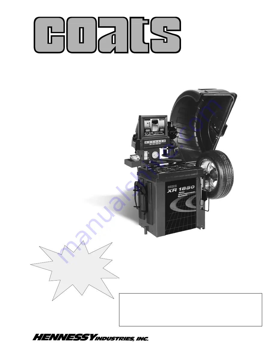
XR 1800/1850 Series
Wheel Balancer
Installation Instructions
Operating Instructions
Safety Instructions
Maintenance Instructions


