Henkelman Jumbo 30, User Manual
The Henkelman Jumbo 30 is an innovative vacuum packaging machine designed for professional use. Ensure optimal performance by referring to the User Manual available for free download from manualshive.com. This comprehensive manual provides step-by-step instructions on how to operate and maintain your vacuum packaging machine effectively.
Share
Download


Reviews:
No comments
Related manuals for Jumbo 30
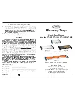
WT-100
Brand: Cadco Pages: 2
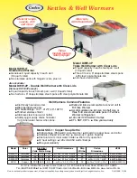
DWW-11
Brand: Cadco Pages: 1

67880
Brand: Lund Pages: 16

SP2111
Brand: Salton Pages: 8

1509325
Brand: MS Schippers Pages: 28

WCW10
Brand: Waring Pages: 24

HZ31
Brand: inventum Pages: 36

ABAYA ETB01-15
Brand: HEALLUX Pages: 21

SealerSales CBS-880I
Brand: MyBinding Pages: 46

InductWarm Built-in 200
Brand: Gastros Pages: 8

1995S
Brand: PARRY Pages: 13

Neuro Fuzzy NS-ZCC10
Brand: Zojirushi Pages: 26

Timelis
Brand: Atlantic Pages: 16

500-E
Brand: Alto-Shaam Pages: 2

106524
Brand: Monzana Pages: 10

HEC-104
Brand: Henny Penny Pages: 5

Wendy's MPC-21L
Brand: Henny Penny Pages: 12

BW-1
Brand: Henny Penny Pages: 2


