background image

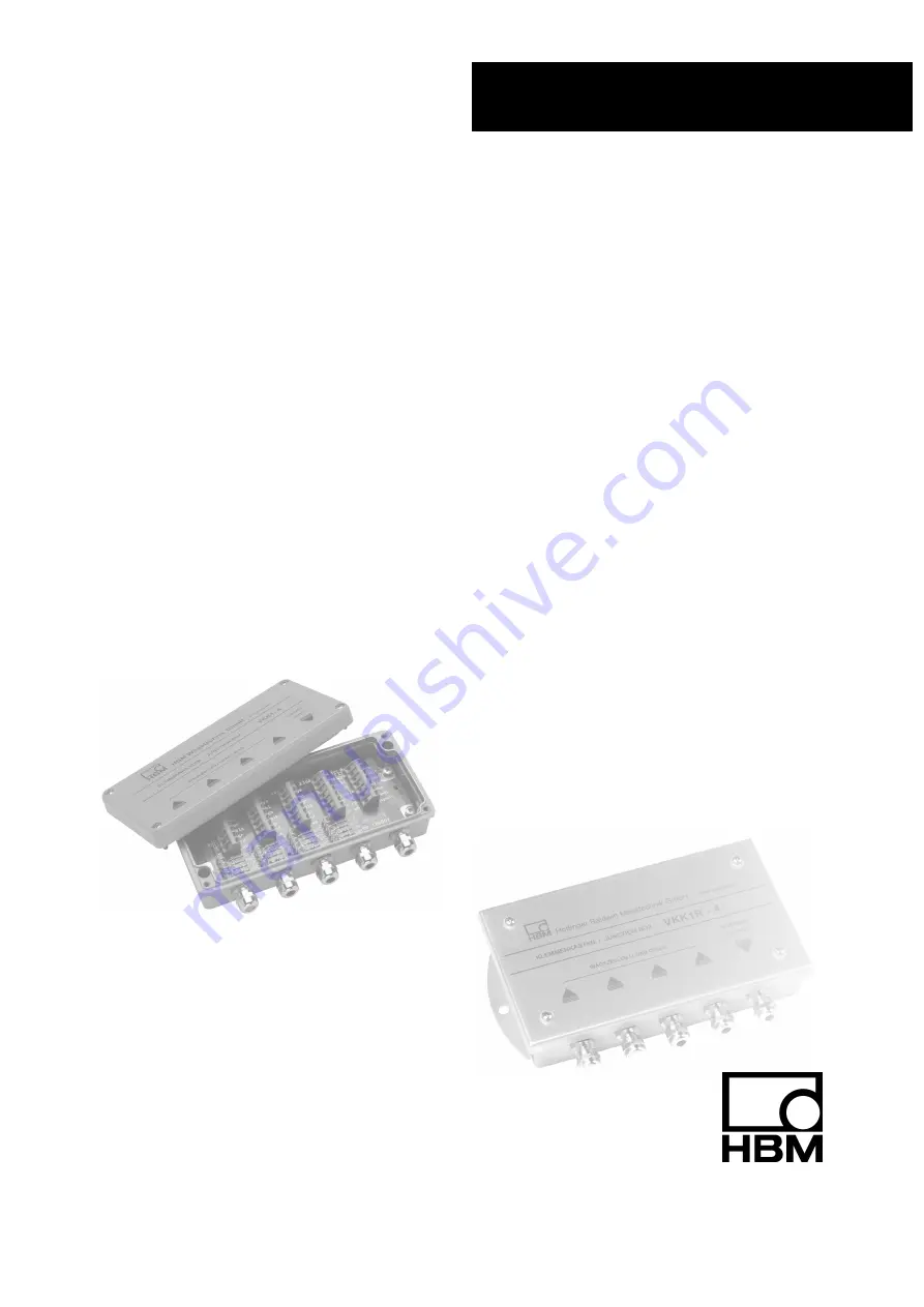
VKK1R4

VKK14

A23261.0en/de/fr

Junction  boxes
Klemmenkästen
Boîtiers  de  raccordement

VKK14
VKK1R4

Mounting  instructions

Montageanleitung

Notice  de  montage

Summary of Contents for VKK1-4

Page 1: ...VKK1R 4 VKK1 4 A2326 1 0 en de fr Junction boxes Klemmenk sten Bo tiers de raccordement VKK1 4 VKK1R 4 Mounting instructions Montageanleitung Notice de montage...

Page 2: ...English Page 3 16 Deutsch Seite 17 30 Fran ais Page 31 44...

Page 3: ...ling the terminal boxes 8 2 1 Mounting dimensions VKK1 4 VKK1R 4 8 2 2 Tightening the mounting screws of the cover plate 9 3 Preparing the cables 10 4 Connection 11 5 Corner load balancing 12 6 Techni...

Page 4: ...n this terminal box must not only be correctly transported stored sited and installed but must also be carefully operated and maintained General dangers of failing to follow the safety instructions Th...

Page 5: ...s could lead to damage to property and slight or moderate physical injury Qualified personnel The terminal box must only be installed by qualified personnel strictly in accordance with the specificati...

Page 6: ...arry out any repairs and soldering work on the motherboards or to replace any components Repairs may only be carried out by persons authorized thereto by Hottinger Baldwin Messtechnik GmbH During inst...

Page 7: ...01 Corner load balancing via the integrated resistor network in the load cell output Degree of protection IP65 to EN 60 529 The terminal boxes also allow the screen to be connected conventionally by m...

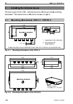
Page 8: ...1 Mounting dimensions VKK1 4 VKK1R 4 Suitable fastening screws M4 DIN 84 or B3 9 DIN 7971 minimum screw length 20 mm 4 6 5 52 163 84 179 50 100 6 18 45 SW14 30 depending on the cable type Grounding s...

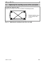
Page 9: ...ounting screws of the cover plate Terminal box viewed from above Tighten the mounting screws of the cover plate in the following sequence 1 4 2 3 Maximum tightening torque of the mounting screws 2 5 N...

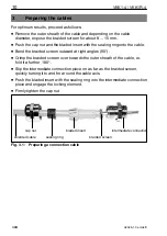
Page 10: ...en outward at right angles 90 D Crimp the braided screen over towards the outer sheath of the cable i e fold it a further 180 D Slip the intermediate connection piece on as far as the braided screen q...

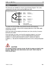
Page 11: ...he weighing electronics with HBM cables using 6 wire circuitry If the load cells and the weighing electronics use 4 wire circuitry the sense terminals are unused If the load cells use 4 wire circuit a...

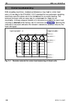
Page 12: ...compensate for these errors electrically A binary stepped network of 4 resistors is available for each load cell that is shorted at the factory via 0 resistors see Fig 5 1 Opening the vertical 0 resis...

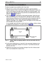
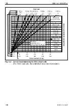
Page 13: ...intersection with the test load and then on the Y axis read off the resistance and the most suitable combination The resistance values here apply for 350 load cells see the table in the lid of the VK...

Page 14: ...250 kg 2 5 t 25 t 300 kg 3 t 30 t 0 39 0 82 1 5 3 0 39 1 5 3 1 5 3 0 39 0 82 3 0 82 3 0 39 3 3 0 39 0 82 1 5 0 82 1 5 0 39 1 5 1 5 0 39 0 82 0 82 0 39 0 2 2 20 1 10 100 2 20 200 3 30 300 4 40 400 5 5...

Page 15: ...s resistance will be added to that of the network If the chart is not big enough the adjustment resistance can be calculated as follows R EA adjustment resistance R AW output resistance of the load ce...

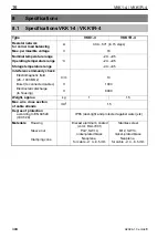
Page 16: ...ce immunity check Electromagnetic field 26 1000 MHz V m 10 Burst to connected cables V 1000 Electrostatic discharge to housing V 6000 Weight approx kg 1 1 5 Max wire cross section of cable strands mm2...

Page 17: ...1 2 Montage der Klemmenk sten 22 2 1 MontageabmessungenVKK1 4 VKK1R 4 22 2 2 Anziehen der Montageschrauben des Deckels 23 3 Konfektionierungder Kabel 24 4 Anschlie en 25 5 Eckenlastabgleich 26 6 Techn...

Page 18: ...kastens setzt sachgem en Transport fachgerechte Lagerung Aufstellung und Montage sowie sorgf ltige Bedienung und Instandhaltung voraus Allgemeine Gefahren bei Nichtbeachten der Sicherheitshinweise De...

Page 19: ...al Der Klemmenkasten ist nur von qualifiziertem Personal ausschlie lich ent sprechend der technischen Daten in Zusammenhang mit den nachstehend ausgef hrten Sicherheitsbestimmungen und Vorschriften ei...

Page 20: ...e ein Austauschen von Bauteilen ist strengstens untersagt Reparaturen d rfen ausschlie lich durch von der Hottinger Baldwin Messtechnik GmbH autorisierte Personen ausgef hrt werden Treffen Sie bei der...

Page 21: ...mungskonzept Eckenlastabgleich ber integriertes Widerstandsnetzwerk im W gezellenausgang Schutzart IP65 nach EN 60 529 Die Klemmenk sten bieten auch die M glichkeit den Schirmanschluss her k mmlich mi...

Page 22: ...de Feuchtigkeit erh ht 2 1 Montageabmessungen VKK1 4 VKK1R 4 Geeignete Befestigungsschrauben M4 DIN 84 oder B3 9 DIN 7971 Schraubenl nge min 20mm 4 6 5 52 163 84 179 50 100 6 18 45 SW14 30 je nach Kab...

Page 23: ...Anziehen der Montageschrauben des Deckels Draufsicht des Klemmenkastens Montageschrauben des Deckels in folgender Reihenfolge anziehen 1 4 2 3 Maximales Anzugsmoment der Montageschrauben 2 5 N m Abb 2...

Page 24: ...l schieben D Schirmgeflecht rechtwinklig 90 nach aussen biegen D Schirmgeflecht in Richtung Aussenmantel umfalzen d h nochmals um 180 umlegen D Zwischenstutzen bis zum Schirmgeflecht aufstecken und ku...

Page 25: ...W geelektronik er m glicht bestm gliche Messergebnisse und eine optimale St rfestigkeit Sind die W gezellen und die W geelektronik in 4 Leitertechnik bleiben die F hlerklemmen frei Sind die W gezelle...

Page 26: ...f r ist f r jede W gezelle ein bin r gestuftes Netzwerk aus 4 Wider st nden vorhanden das werkseitig ber 0 Widerst nde kurzgeschlossen ist siehe Abb 5 1 Durch Auftrennen der senkrechtstehenden 0 Wider...

Page 27: ...den Schnittpunkt mit der Pr flast und kann auf der Y Achse den Widerstand und die bestpassende Kombination ablesen Die Widerstandswerte gelten hier f r 350 W gezellen siehe Tabelle im Dec kel der VKK...

Page 28: ...250 kg 2 5 t 25 t 300 kg 3 t 30 t 0 39 0 82 1 5 3 0 39 1 5 3 1 5 3 0 39 0 82 3 0 82 3 0 39 3 3 0 39 0 82 1 5 0 82 1 5 0 39 1 5 1 5 0 39 0 82 0 82 0 39 0 2 2 20 1 10 100 2 20 200 3 30 300 4 40 400 5 5...

Page 29: ...ei gener Wahl ersetzt werden Dieser Widerstand addiert sich zu dem des Netz werkes Wenn das Diagramm nicht ausreicht kann der Abgleichwiderstand wie folgt berechnet werden R EA R AW L E L P R EA Abgle...

Page 30: ...festigkeitspr fung Elektromagnetisches Feld 26 1000 MHz V m 10 Burst auf angeschlossene Kabel V 1000 Elektrostatische Entladung auf Geh use V 6000 Gewicht ca kg 1 1 5 Max Aderquerschnitt der Kabellitz...

Page 31: ...ment 36 2 1 Dimensions de montage VKK1 4 VKK1R 4 36 2 2 Serrage des vis de montage du couvercle 37 3 Confection des c bles VKK1 4 VKK1R 4 38 4 Raccordement 39 5 Equilibrage des charges d angle 40 6 Re...

Page 32: ...stockage une installation et un montage appropri s et d assurer un maniement ainsi qu un entretien scrupuleux Risques g n raux en cas de nonrespect des consignes de s curit Le bo tier de raccordement...

Page 33: ...essures corporelles de gravit minime ou moyenne Personnel qualifi Le bo tier de raccordement doit uniquement tre manipul par du personnel qualifi conform ment aux caract ristiques techniques et aux co...

Page 34: ...une r paration ou une soudure sur les circuits imprim s ou de remplacer des composants Les r parations ne doivent tre effectu es que par des personnes autoris es par Hottinger Baldwin Messtechnik GmbH...

Page 35: ...rges d angle par r seau de r sistances int gr dans la sortie du peson Degr de protection IP 65 selon EN 60 529 Le bo tier de raccordement offre galement la possibilit de r aliser le blindage de fa on...

Page 36: ...te p n tration d humidit 2 1 Dimensions de montage VKK1 4 VKK1R 4 Vis de fixation appropri es M4 DIN 84 ou B3 9 DIN 7971 longueur de vis mini 20 mm 4 6 5 52 163 84 179 50 100 6 18 45 s p 14 30 selon l...

Page 37: ...rrage des vis de montage du couvercle Vue de dessus du bo tier de raccordement Serrer les vis de montage du couvercle dans l ordre suivant 1 4 2 3 Couple de serrage maximal des vis de montage 2 5 N m...

Page 38: ...blindage angle droit 90 vers l ext rieur D Replier la tresse de blindage vers la gaine ext rieure c d la plier encore de 180 D Enfoncer le manchon interm diaire jusqu la tresse de blindage et le tour...

Page 39: ...fils permet d obtenir les meilleurs r sultats de mesure possibles et une immunit aux parasites optimale Si les pesons et l lectronique de pesage sont raccord s en technique 4 fils les bornes pour l me...

Page 40: ...r ces erreurs de mani re simple par voie lectrique Un r seau binaire de 4 r sistances est donc associ chaque peson ce r seau tant court circuit en usine par des r sistances de 0 voir Fig 5 1 La s para...

Page 41: ...echerche l intersection avec la charge d preuve On peut alors lire sur l axe Y la r sistance et la combinaison la mieux adapt e Les valeurs de r sistance indiqu es ici s appliquent des pesons de 350 v...

Page 42: ...250 kg 2 5 t 25 t 300 kg 3 t 30 t 0 39 0 82 1 5 3 0 39 1 5 3 1 5 3 0 39 0 82 3 0 82 3 0 39 3 3 0 39 0 82 1 5 0 82 1 5 0 39 1 5 1 5 0 39 0 82 0 82 0 39 0 2 2 20 1 10 100 2 20 200 3 30 300 4 40 400 5 50...

Page 43: ...cer par une r sistance de son choix Cette r sistance s ajoute alors celle du r seau Si le graphique ne suffit pas la r sistance d quilibrage peut tre calcul e comme suit R EA R AW L E L P R EA r sista...

Page 44: ...Essai d immunit au bruit Champ lectromagn tique 26 1000 MHz V m 10 Train d impulsions sur c ble raccord V 1000 D charges lectrostatiques sur bo tier V 6000 Poids env kg 1 1 5 Diam tre conducteur maxi...

Page 45: ...45 VKK1 4 VKK1R 4 A2326 1 0 en de fr HBM...

Page 46: ...46 VKK1 4 VKK1R 4 A2326 1 0 en de fr HBM...

Page 47: ......

Page 48: ...forme g n rale Elles n tablissent aucune assurance formelle au terme de la loi et n engagent pas notre responsabilit 7 2001 2326 Modifications reserved All details describe our products in general fo...

Reviews: