background image

HANSA NEW ZEALAND  

            +64 7 849 4749                [email protected] 

             www.hansachippers.com 

HANSA AUSTRALIA 

            1800 426 722                   [email protected] 

            www.hansaproducts.com.au 
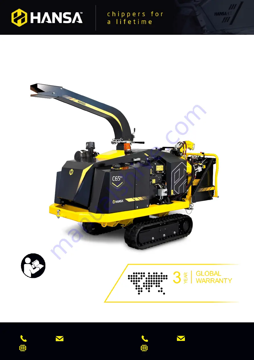


HANSA


C65RX 

Operation, maintenance, and safety manual


All operators must fully read and understand 

this operator’s manual

 before using the chipper. 

Keep this manual for future reference. 

Register your Hansa chipper to qualify 
www.hansaproducts.com/registration 

Summary of Contents for C65RX

Page 1: ...info hansaproducts com au www hansaproducts com au HANSA C65RX Operation maintenance and safety manual All operators must fully read and understand this operator s manual before using the chipper Keep...

Page 2: ...E FEATURE 13 STARTING PROCEDURE 14 SHUTDOWN PROCEDURE 15 RUBBER TRACK DRIVE 16 MANUAL MODE 16 TRACK CONTROL REMOTE PAIRING UNPAIRING PROCEDURE 17 TROUBLESHOOTING 18 MAINTENANCE SERVICE 19 WARNINGS 19...

Page 3: ...igned to be used on by commercial arborists tree contractors and hire rental companies Do NOT use the chipper for any other purpose Organic wastes include Prunings stalks roots vegetable matter hay gr...

Page 4: ...Hansa C65RX O M Manual OM 029 First Release 4 05 2021 Hansa Chippers 2021 2 Chipper overview...

Page 5: ...cut materials and or wear a dust mask Exhaust Fumes Respiratory irritation Place the chipper in a manner that the operator or onlookers are not exposed to direct exhaust fumes Hot Exhaust Heat burns K...

Page 6: ...or other guard it is recommended to use the handles provided Petrol oil grease Poisoning skin irritation harmful vapours Take care when handling petrol oil and grease Wash skin if contaminated with pe...

Page 7: ...n the joysticks are returned to their resting positions Be careful not to release the joysticks too quickly as the brakes could destabilise the machine especially on steep terrain Avoid the following...

Page 8: ...tlined below Ensure the rope wraps around the drum at least five times Do NOT extend the rope past this point Winches operate on the friction principle with less than five wraps the rope will separate...

Page 9: ...glasses and hearing protection must be worn at all times Wear work gloves The wearing of work gloves is optional but highly recommended ensure that the gloves fit tightly Do NOT wear loose fitting gl...

Page 10: ...comes wrapped around the rotor shaft remove it before it works itself into the bearing Process old materials such as dried wooden branches They get very hard and springy when dried out They are more a...

Page 11: ...e machine Adjust outlet rotation direction disengage the lock pin down loosen the rotation crank handle change outlet direction then tighten the rotation crank handle to lock into position Adjust outl...

Page 12: ...er A sensor detects the speed of the cutting rotor once this speed drops to a pre set level the feed roller stops the material feeding into the machine The engine then recovers to higher RPM and once...

Page 13: ...OK to enter Trip Setting highlighted in blue Use the arrows to navigate up and down settings Push OK to change the active trip setting to the highlighted setting highlighted in blue Once the desired s...

Page 14: ...The winch is operated via a control panel near the base of the winch unit The switch on the right controls whether the winch is being extended or retracted The switch on the left toggles between remo...

Page 15: ...azard danger to an operator or onlooker After the rotor comes to a halt follow the normal shutdown procedure in addition to using the emergency stop Inspect the machine before resetting the emergency...

Page 16: ...y must be turned back to the off position before attempting to start again At this point you can use the track control remote to move the machine follow the procedure outlined in the rubber track driv...

Page 17: ...elt friction may cause damage Allow the engine to cool down by running at idle for at least 1 2 minutes before shutting down Turn the ignition key anti clockwise into the off position to shut the chip...

Page 18: ...e switch with two settings full speed hare symbol and reduced speed tortoise symbol It is recommended to keep the speed setting at reduced speed until the operator becomes familiar with the controls T...

Page 19: ...indicating that it is paired to the remote Drive the C65RX to the desired position using the left and right track controls on the remote For safety reasons the feed roller is disabled while the tracks...

Page 20: ...is then close and lock the outlet chute Outlet chute is blocked Outlet is pasted with wet leafy material Feed hard dry material in with softer material Turn the engine off and ensure rotor has complet...

Page 21: ...d cutting rotor stopped the feed roller area can be accessed safely Do NOT attempt to access this area unless the engine is off and rotor has stopped turning If your machine is not fitted with the Lif...

Page 22: ...cutting rotor WARNING Do NOT open rotor cover when engine is on and or rotor is still spinning Ensure rotor has stopped spinning Remove the two bolts from rotor cover and disconnect the rubber bonnet...

Page 23: ...key Torque wrench with a 24 mm socket and 16mm crows foot wrench A stick magnet optional Surface grinder Coolant Remove the knives for sharpening Open the rotor housing cover by removing the two housi...

Page 24: ...dure Torque the knife clamping nuts up to 190 Nm Note Torque the nuts while holding the bolt head stationary to ensure correct torque After sharpening the width of the knives will have been reduced th...

Page 25: ...in this manual To remove the anvil you must remove the four countersink clamping bolts using an 18 mm socket and extension If the bolt head turns hold it with a 6 mm Allen key Note Do NOT use the Alle...

Page 26: ...Checking and setting belt tension With the engine off fully engage the cutting rotor Check the angle of the blue tensioner device When the engagement handle is fully engaged this should be bent 20 as...

Page 27: ...ess 3 Tighten the locknuts against each other 4 Turn the engagement handle fully clockwise and check tension again 5 Reinstall the guard Belt replacement If the belts in your chipper look similar to a...

Page 28: ...t the belt about 3 to 5 mm when pushing firmly in the middle of the belt span The belt can be adjusted by loosening the four mounting bolts on the pump bracket bracket shown in blue below and moving t...

Page 29: ...elow must be greased every 50 operating hours with bearing grease or all purpose grease 1 Two bearings on the cutting rotor shaft one on the front side of the housing and one on the rear 2 One bearing...

Page 30: ...outlet chute two underneath the front edge 5 One grease nipple on the engine engagement screw thread Remove the Engagement Guard to reach the grease nipple by removing the 3 mounting bolts 6 One grea...

Page 31: ...to the engine manual Change oil oil filter fuel filter and air filter as recommended in the manual Ensure the correct engine oil is used C65RX Track maintenance and rubber track tension Please refer...

Page 32: ...ulley is tightened evenly 6 The gap between the end of the sensor and the sensing plate should be approximately 4 mm Adjust the sensor accordingly If it is set further away then the sensor may not wor...

Page 33: ...initial change Initial Hydraulic system check Engine fan belt check Engine oil filter change Hydraulic oil filter replace Battery electrolyte level terminals check Engine fuel filter replace Outlet c...

Page 34: ...m Tracked Undercarriage Speed 5 km hr max fully proportional Track drive Remote control Track material Rubber Cutting System Disc speed 1700 RPM Disc diameter 800 x 40 mm Shaft diameter 60 mm Knives F...

Page 35: ...pers 2021 33 Decals Decal Description Location General machine safety and inlet chute safety Side of inlet chute both sides Inlet chute safety Inside of inlet table Rotor engagement control Belt guard...

Page 36: ...l OM 029 First Release 4 05 2021 Hansa Chippers 2021 34 Weekly service checks Rotor cover RH side Start procedure Under display screen Stop procedure Under start procedure Remote Start Stop procedure...

Page 37: ...a C65RX O M Manual OM 029 First Release 4 05 2021 Hansa Chippers 2021 35 Outlet chute safety Outlet chute Service schedule Electrical box lid Diesel tank Diesel tank Hydraulic oil tank Hydraulic oil t...

Page 38: ...roller cover and guard safety keep clear Feed roller cover RH side Feed roller guard safety keep clear Feed roller guard RH side Feed roller guard safety keep clear Feed roller guard LH side Bonnet d...

Page 39: ...Note This label is only applicable to C65RX models fitted with a winch Winch boom control panel side Rotor cover safety Rotor cover LH side near throttle Hydraulic oil fill level On hydraulic tank Lab...

Page 40: ...ranty is available to domestic non commercial and commercial customers excluding commercial customers in the business of plant equipment hire All HANSA products that have not complied with the Extende...

Page 41: ...you purchased your HANSA product Conditional Warranty This is a HANSA extended warranty period for products that are Purchased from an authorised HANSA Dealer Registered at the time of sale through th...

Page 42: ...peration Instruct the owner operator on operating procedures and techniques Safety Instruct owner operator on safety procedures Maintenance Explain the maintenance requirements and the importance of f...

Reviews: