background image

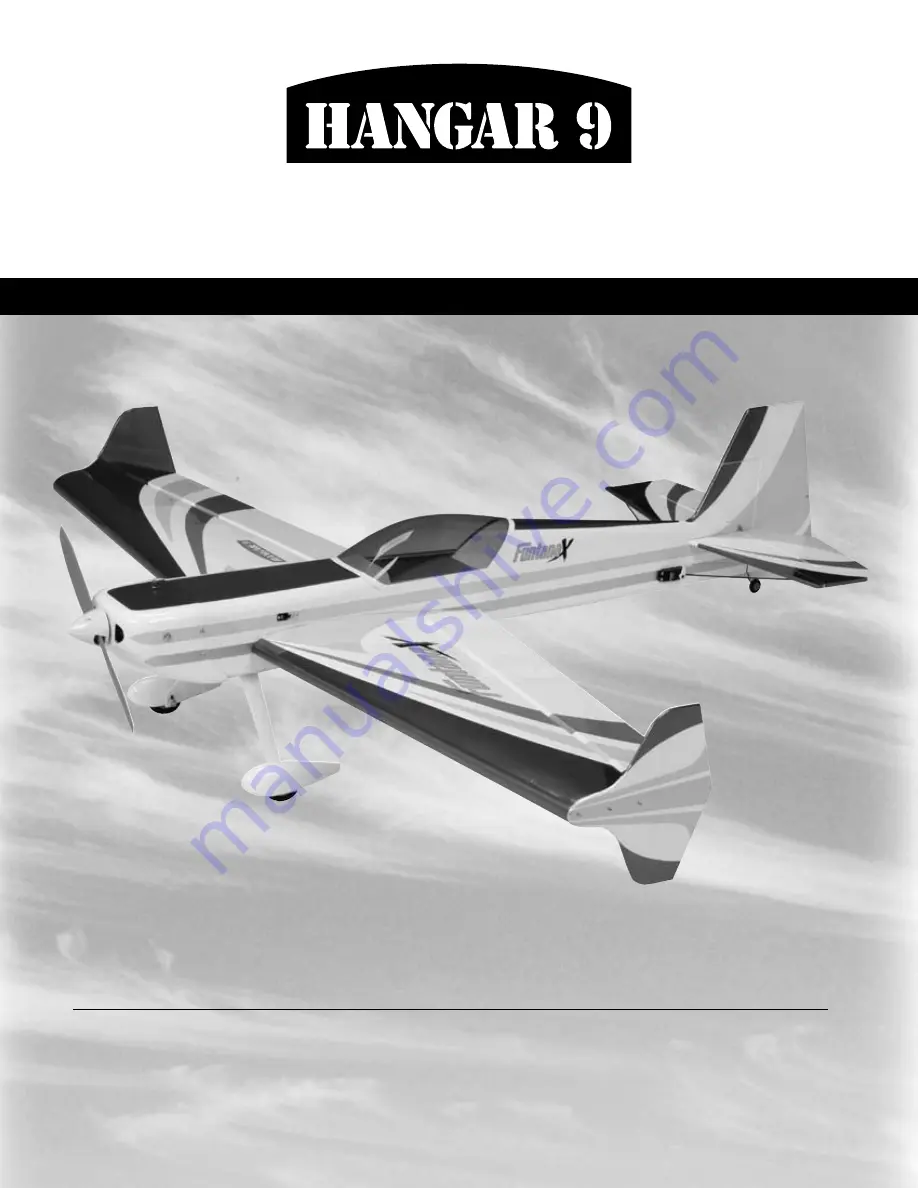
Wingspan:  ..................................... 56 in (1422mm)

Length:  .......................................... 56 in (1441mm)

Wing Area:  ......................... 714 sq in (46.1 sq dm)

Assembly mAnuAl

FuntanaX 50 ARF

Weight: ............................  4–5.5 lb (1.8 kg–2.5 kg)

Radio:  ..................................  4-channel w/5 servos

Engines:  ...........  32–.46 2-stroke, .40–.72 4-stroke

Specifications

5.

ƒ

Summary of Contents for FuntanaX 50

Page 1: ...n 56 in 1422mm Length 56 in 1441mm Wing Area 714 sq in 46 1 sq dm Assembly manual FuntanaX 50 ARF Weight 4 5 5 lb 1 8 kg 2 5 kg Radio 4 channel w 5 servos Engines 32 46 2 stroke 40 72 4 stroke Specifications 5 ...

Page 2: ... Using the Manual 7 Before Starting Assembly 7 Section 1 Stabilizer Installation 8 Section 2 Vertical Fin Installation 11 Section 3 Hinging the Ailerons 12 Section 4 Rudder and Elevator Installation 14 Section 5 Wheel Installation 16 Section 6 Engine Installation 18 Section 7 Cowling Installation 22 Section 8 Servo Installation 24 Section 9 Linkage Installation 26 Section 10 Final Assembly 30 Cent...

Page 3: ...ead Extension JRPA097 2 12 Servo Lead Extension JRPA098 2 Large Servo Arm JRPA212 2 Propeller low pitch large diameter recommended Recommended JR Systems PCM10X XP8103 X 378 XP662 XF631 Recommended Power Systems 40 48 2 stroke 40 82 4 stroke Power 60 Brushless Outrunner JR XP6102 JR XP9303 Evolution 46NT EVOE0460 Saito 82 AAC SAIE082A Power 60 Brushless Outrunner Motor 400KV EFLM4060A Large Parts ...

Page 4: ...DAMAGES As Horizon Hobby Inc has no control over use setup final assembly modification or misuse no liability shall be assumed nor accepted for any resulting damage or injury By the act of use setup or assembly the user accepts all resulting liability If you as the purchaser or user are not prepared to accept the liability associated with the use of this product you are advised to return this prod...

Page 5: ...uct will be repaired or replaced free of charge Repair or replacement decisions are at the sole discretion of Horizon Hobby Non Warranty Repairs Should your repair not be covered by warranty and the expense exceeds 50 of the retail purchase cost you will be provided with an estimate advising you of your options You will be billed for any return freight for non warranty repairs Please advise us of ...

Page 6: ...ves 6 minute epoxy HAN8000 30 minute epoxy HAN8002 Thin CA cyanoacrylate glue Thick CA cyanoacrylate glue CA remover debonder Pacer Z 42 Threadlock Canopy glue RC 56 Masking tape 3M blue recommended Other Required Items Epoxy brushes Felt tipped pen or pencil Measuring device e g ruler tape measure Mixing sticks for epoxy Paper towels Petroleum jelly Radio packing foam Rubbing alcohol Sanding bar ...

Page 7: ...s between each major section In addition check boxes have been placed next to each step to keep track of each step completed Steps with a single box are performed once while steps with two boxes indicate that the step will require repeating such as for a right or left wing panel two servos etc Remember to take your time and follow the directions Before Starting Assembly Before beginning the assemb...

Page 8: ... Sandpaper Drill bit 1 16 1 5mm Drill Felt tipped pen Square CA hinge 6 Paper towel Rubbing alcohol T pin 6 minute epoxy Step 1 Place the wing onto the fuselage Secure the wing using the 1 4 20 x 2 nylon bolts Step 2 Measure and mark a centerline on the stabilizer using a felt tipped pen Step 3 Locate six CA hinges Place a T pin in the center of each hinge Section 1 Stabilizer Installation ...

Page 9: ...m the stabilizer Use tape at each tip to hold the two together Do not use CA or any other glue on the hinges at this time Step 7 Slide the stab into the fuselage Center the stab in the opening by measuring the distance from the fuselage to each tip The stab is aligned when both measurements are identical Step 8 Check the distance from each stab tip to each wing tip Remember to measure right to rig...

Page 10: ...on to the standard hobby knife Cool Tip Use a little rubbing alcohol and a paper towel to remove those felt tipped marker lines once they are no longer needed Step 12 Double check the alignment to verify it s correct Mix up 1 2 ounce 15 ml of 30 minute epoxy Apply the epoxy to the exposed wood of the stabilizer and into the slot in the fuselage Slide the stabilizer into position and remove any exc...

Page 11: ... the stab to be in alignment Sand the opening in the fuselage slightly if necessary to get the perfect alignment Step 3 Use a ruler to draw two lines from the end of the slot onto the fuselage as shown Use a sharp hobby knife to remove the covering from between the lines Step 4 Mix 1 2 ounce 15ml of 30 minute epoxy Apply the epoxy to the tab on the fin and to the area on the top of the fuselage wh...

Page 12: ...he aileron and wing Step 3 Place the hinges in the precut slots in the aileron or wing if you prefer The T pin will rest against the edge when installed correctly Step 4 Slide the aileron and wing together The gap between the aileron and wing should be infinitely small approximately 1 64 4mm Step 5 Use a ruler to align the end of the aileron to the wing The aileron should set back away from the ru...

Page 13: ...y saturated with CA Use a paper towel and CA remover debonder to clean up any excess CA from the wing and or aileron Step 7 Firmly grasp the wing and aileron and gently pull on the aileron to ensure the hinges are secure and cannot be pulled apart Use caution when gripping the wing and aileron to avoid crushing the structure Step 8 Move the aileron up and down several times to work in the hinges a...

Page 14: ...e the hinge and don t use accelerator Step 2 Once the CA has fully cured give the elevator and stab the tug test to make sure the hinges are well glued Flex the elevator a few times to break in the hinges Step 3 Apply a light coat of petroleum jelly onto the tail gear wire where the bearing will ride This is done to prevent the epoxy from sticking to the wire and bearing which would make it a litt...

Page 15: ...udder Install the rudder as described in the previous step Cool Tip You can combine the previous step with the following step if you like This will hold the rudder in position while the epoxy cures Step 8 Check to make sure the rudder moves freely It should not rub against the fin at the tip Apply thin CA to both sides of the hinge Make sure to saturate the hinge and don t use accelerator Use a pa...

Page 16: ... 2 screws Attach the gear using the screws The angle on the gear should be towards the rear of the plane Step 2 Attach an axle to the landing gear using a nut Step 3 Attach the wheel to the axle using two wheel collars and setscrews The exact position of the wheel will be determined after the wheel pant is installed Cool Tip Position the setscrews on the wheel collars facing directly down This way...

Page 17: ...hten the collars once the wheel has been positioned Step 6 Repeat Steps 2 through 5 for the other wheel pant Step 7 Attach the tail wheel using a 5 32 wheel collar Note Use threadlock on all the setscrews to prevent them from loosening during flight Section 5 Wheel s On ...

Page 18: ... 6 32 x 3 4 screws Step 2 Position the engine on the mount Adjust the engine so the distance from the firewall to the drive washer is 4 1 2 114mm Use a clamp to hold the engine in position Mark the locations for the engine mounting bolts Note It may be necessary to remove the carburetor from your engine and rotate it so the needle valve faces towards the top of the fuselage Step 3 Remove the engin...

Page 19: ...hrod Mark the location with a felt tipped pen and drill the firewall for the pushrod tube using a drill and 5 32 4mm drill bit Remove the engine if necessary Step 6 Test fit the throttle pushrod tube through the firewall and into the fuselage Once satisfied with the fit roughen the tube using sandpaper Slide the tube back into position and use medium CA to glue it to the firewall Allow 1 8 3mm of ...

Page 20: ...servo Mount the throttle servo with the output shaft towards the rear of the fuselage Step 9 Slide the pushrod into place from inside the fuselage and attach the clevis to the servo arm Step 10 Move the carburetor to the half throttle position Mark the pushrod where it crosses the throttle arm using a felt tipped pen Remove the pushrod and make a Z bend in the pushrod Section 6 Engine Installation...

Page 21: ...range of operation Step 13 Look at the side of the fuel tank to determine which direction the vent line is facing It will be installed with the vent towards the top of the fuselage Also check which piece of tubing is connected to the vent line Install the fuel tank into the fuselage Place foam at any point where the fuel tank and fuselage contact each other Make any necessary supports to keep the ...

Page 22: ...wl Step 3 Remove the cowl and remove the necessary material to fit the cowl over the engine Install the engine back onto the firewall and test fit the cowl over the engine Cool Tip Start by removing only a little material at a time You can always make the holes bigger but you can t make them smaller Work until the cowl fits nicely over the engine Step 4 Slide the cowling onto the fuselage Temporar...

Page 23: ...illed in the cowling using a 1 8 3mm drill bit Step 7 Apply a couple drops of CA into the screw holes after threading the screws in a few times This will harden the wood and keep the screws from loosening during flight Step 8 Remove a section of the cowl bottom to allow air to escape the cowling Step 9 Attach the cowl using four 2 x 1 2 sheet metal screws Step 10 Attach the propeller and spinner o...

Page 24: ...s using a 1 16 1 5mm drill bit Cool Tip Place a drop of thin CA onto each screw hole to harden the wood around the hole Allow the CA to fully cure before installing the servos Step 4 Attach an 18 457mm servo extension onto the rudder servo Use you favorite method to secure the extension to prevent it from coming loose during flight Secure the rudder servo using the screws provided with the servo S...

Page 25: ...ware provided with the servo The output shaft of the servo faces towards the trailing edge of the wing Step 9 Repeat Steps 6 through 8 for the other aileron servo Step 10 Wrap the receiver and receiver battery in protective foam to prevent damage that may be caused by engine vibration Step 11 Temporarily mount the receiver and battery into the fuselage It may be necessary to relocate the battery f...

Page 26: ...river small Step 1 Slide a clevis retainer onto a nylon clevis Thread a clevis onto a 7 7 8 200mm wire a minimum of 10 turns Step 2 Attach a heavy duty servo arm JRPA215 to the elevator servo Remove the back plate from a control horn using side cutters or a sharp hobby knife Attach the clevis to the outer hole of the control horn Position the control horn on the elevator so the horn aligns with th...

Page 27: ... for each of the three holes Step 4 Attach the control horn using three 2 56 x 1 2 screws and the control back plate Step 5 Physically place the elevator control surface in neutral Mark the pushrod where it crosses the holes in the servo arm Step 6 Bend the wire 90 degrees at the mark made in the previous step Cut the wire 1 2 13mm above the bend Section 8 Servo Installation ...

Page 28: ...s Step 10 Remove the back plate from a control horn using side cutters or a sharp hobby knife Attach the clevis to the control horn After installing a heavy duty servo arm position the control horn on the aileron so the horn aligns with the hinge line of the aileron With the aileron servo deflected for full throw position the pushrod so it is perpendicular to the hinge line as it crosses the servo...

Page 29: ... electronically using the radio system Install a servo arm onto the aileron servo Attach the pushrod with clevis to the control horn Physically place the aileron control surface in neutral Mark the pushrod where it crosses the holes in the servo arm Bend the wire 90 degrees at the mark made in the previous step Cut the wire 1 2 13mm above the bend Slide the wire through the outer hole in the ailer...

Page 30: ...py and fuselage using a paper towl and rubbing alcohol Be careful not to remove the line from the fuselage Step 4 Apply a bead of Canopy Glue around the inside edge of the canopy Position the canopy onto the hatch Use tape to hold the canopy secure until the glue fully cures Step 5 Once the canopy gule has fully cured use a paper towel and rubbing alcohol to remove the lines from the fuselage Appl...

Page 31: ...Center of Gravity The following control throws offer a good place to start with your first flights We recommend only one rate setting for the FuntanaX 50 As you become more familiar with the handling of your model you may wish to add a second rate setting Low Rates Aileron 3 4 19mm 9 up 5 8 16mm 6 down Elevator 7 8 23mm 11 up 7 8 23mm 11 down Rudder 2 51mm 25 left 2 51mm 25 right 3D Rates Aileron ...

Page 32: ...ms that would be considered questionable Failure of any of these components in flight would mean the loss of your aircraft Adjusting the Engine Step 1 Completely read the instructions included with your engine and follow the recommended break in procedure Step 2 At the field adjust the engine to a slightly rich setting at full throttle and adjust the idle and low speed needle so that a consistent ...

Page 33: ...33 Notes ...

Page 34: ...explosive gases such as hydrogen filled balloons or ground mounted devices launching a projectile The only exceptions permitted are rockets flown in accordance with the National Model Rocketry Safety Code or those permanently attached as per JATO use also those items authorized for Air Show Team use as defined by AST Advisory Committee document available from AMA HQ In any case models using rocket...

Page 35: ...used no powered model may be flown closer than 25 feet to any person 9 Under no circumstances may a pilot or other person touch a powered model in flight Organized RC Racing Event 10 An RC racing event whether or not an AMA Rule Book event is one in which model aircraft compete in flight over a prescribed course with the objective of finishing the course faster to determine the winner A In every o...

Page 36: ... 2006 Horizon Hobby Inc 4105 Fieldstone Road Champaign Illinois 61822 877 504 0233 horizonhobby com 8685 5 ...

Reviews: