Installation
INSTALLATION AND OPERATION
SMART WI-FI REMOTE CONTROL
Safety Information
Warranty
CAUTION:
Incorrect wire
connections will damage
this receiver.
The supplier warrants the remote control and receiver to be free from defects in
workmanship and material present at time of shipment from the factory for a period of
one year after the date of purchase by the original purchaser. We agree to correct such
defects without charge or at our option replace with a comparable or superior model if
the product is returned. To obtain warranty service, you must present a copy of the
receipt as proof of purchase. All costs of removing and reinstalling the product are your
responsibility. Damage to any part such as by accident or misuse or improper installation
or by affixing any accessories, is not covered by this warranty. Servicing performed by
unauthorized persons shall render the warranty invalid. There is no other express warranty.
Home Depot hereby disclaims any and all warranties, including but not limited to those of
merchantability and fitness for a particular purpose to the extent permitted by law. The
duration of any implied warranty which cannot be disclaimed is limited to the time period
as specified in the express warranty. Some states do not allow a limitation on how long an
implied warranty lasts, so the above limitation may not apply to you. The retailer shall not
be liable for incidental, consequential, or special damages arising out of or in connection
with product use or performance except as may otherwise be accorded by law. Some
states do not allow the exclusion of incidental or consequential damages, so the above
exclusion or limitation may not apply to you. This warranty gives specific legal rights, and
you may also have other rights which vary from state to state. This warranty supersedes all
prior warranties. Shipping costs for any return of product as part of a claim on the warranty
must be paid by the customer.
Contact the Customer Service Team at 1-877-592-5233 or visit HomeDepot.com/hubspace.
Pre-Installation
Step
ladder
Part
Description
Quantity
A
Receiver
1
B
Remote control
1
C
Wire connecting nut
5
D
AAA battery (1.5V)
2
E
Silicone rubber plug
1
F
Wall cradle
1
G
Wall cradle screw
2
H
Plastic anchor
2
I
Rubber isolated pad
2
PACKAGE CONTENTS
IMPORTANT:
This product and/
or components are governed by
one or more of the following U.S.
Patents: 5,947,436; 5,988,580;
6,010,110; 6,046,416, 6,210,117
and other patents pending.
1
NOTE:
The frequencies on your receiver and hand unit have been preset
at the factory. Before installing the receiver, make sure the dip switches
on the receiver and hand unit are set to the same frequency. The dip
switches on the hand unit are located inside the battery compartment.
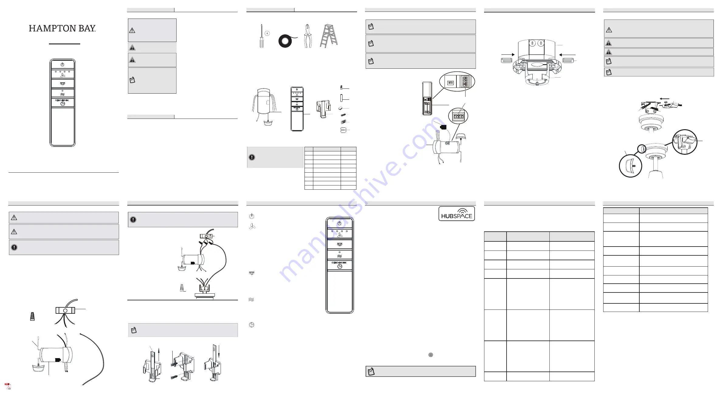
Setting the code on the remote control
Application Set-Up
• Remove the remote control (B)
battery cover by pressing firmly
on the arrow and sliding the
cover off.
• Slide the dip switches (ZZ) to
your choice of either up or down.
The factory setting is up.
• Slide the dip switches (ZZ) on
the receiver (H) to the same
position as set on the remote
control (B).
• Install two 1.5V batteries
(included).
• Replace the battery cover on the
remote control (B).
• Insert the silicone rubber
stopper (E) into the hole on the
receiver (A) to cover the dip
switches.
1
Operating the remote control
This equipment has been tested and found to comply with the limits for a Class B digital device, pursuant
to Part 15 of the FCC Rules. These limits are designed to provide reasonable protection against harmful
interference in a residential installation. This equipment generates, uses and can radiate radio frequency
energy and, if not installed and used in accordance with the instructions, may cause harmful interference
to radio communications. However, there is no guarantee that interference will not occur in a particular
installation. If this equipment does cause harmful interference to radio or television reception, which can
be determined by turning the equipment off and on, the user is encouraged to try to correct the interference
by one or more of the following measures:
--Reorient or relocate the receiving antenna.
--Increase the separation between the equipment and receiver.
--Connect the equipment into an outlet on a circuit different from that to which the receiver is connected.
--Consult the dealer or an experienced radio/TV technician for help.
CAUTION:
Any changes or modifications not expressly approved by the grantee of this device could void the user’s
authority to operate the equipment.
FCC ID: 2AQZU-18016
This device complies with Part 15 of the FCC Rules. Operation is subject to the following two conditions: (1)
This device may not cause harmful interference, and (2) this device must accept any interference received,
including interference that may cause undesired operation.
Item #1006 022 993
Model #76278
CAUTION:
To reduce the risk
of fire or injury, do not use this
product in conjunction with any
variable (rheostat) wall control.
NOTE:
The battery will weaken
with age and should be
replaced before leaking takes
place as this will damage
the hand unit. Dispose of the
used battery properly, keep
the battery out of the reach of
children.
WARNING:
To avoid possible
electrical shock, turn the
electricity off at the main
fuse box before wiring. If you
feel you do not have enough
electrical wiring experience,
contact a licensed electrician.
3
Installing the receiver
WARNING:
To reduce the risk of fire or electric shock, remember to
disconnect power. The electrical wiring must meet all local and national
electrical code requirements. The electrical source and fan must be 110/120
volt, 60Hz. Do not use this product in conjunction with any variable wall
control. Incorrect wire connection can damage this receiver.
CAUTION:
If fan or house wires are a different color, have this unit installed by a
licensed electrician.
CAUTION:
Do not install in a damp location or immerse in water (for indoor use
only). Do not pull on or cut leads shorter. Do not drop or bump the unit.
Installation (continued)
NOTE:
You must set ceiling fan to high speed and light kit (if any) to the
on position using the pull chains (if applicable) before operating remote
control.
NOTE:
For better performance with the WIFI system, the WIFI antenna must
be mounted to the ceiling outside of the fan’s ceiling canopy.
• Position the house supply wires (AAA) to one side of the slide-on mounting
bracket; position the fan wires (BBB) to the opposite side.
• Insert the narrow end of the receiver (as shown, flat side towards the
ceiling) into the slide-on mounting bracket until it rests on top of the ball/
downrod assembly.
Installation (continued)
4
Wiring the receiver to the household wiring
WARNING:
Each wire nut supplied with this fan is designed to accept up
to one 12-gauge house wire and two wires from the fan. If you have larger
than 12-gauge house wiring or more than one house wire to connect to
the fan wiring, consult an electrician for the proper size wire nuts to use.
• Spread the wires apart so that the green and white wires are on one side of the
outlet box and the black wire is on the other side.
• Connect the green fan wires to the household ground wire (this may be a green
or bare wire) using a wire connecting nut (C) supplied by your fan.
• Connect the receiver black (or red) wire to the household black (hot) wire using
a wire connecting nut (C).
• Connect the receiver white wire to the household white wire (neutral) wire
using a wire connecting nut (C).
• Secure each wire connecting nut using electrical tape.
WARNING:
To avoid possible electrical shock, turn the electricity off at the
main fuse box before wiring. If you feel you do not have enough electrical
wiring knowledge or experience, contact a licensed electrician.
Wiring the fan to the receiver
• Connect the fan motor white wire
to the receiver white wire using a
wire connecting nut (C).
• Connect the fan motor black wire
to the receiver black wire using a
wire connecting nut (C).
• Connect the fan motor blue wire
to the receiver blue wire using a
wire connecting nut (C).
• Secure each wire connecting nut
using electrical tape.
• Turn the wire connecting nut (C)
upward and push the wiring into
the outlet box (MM).
5
IMPORTANT:
Use the wire connecting nuts (C) supplied with your remote.
The wire connecting nut (C) for the ground/green wire is supplied with the
fan. Secure the connectors with electrical tape and ensure there are no
loose strands or connections.
Operating Your Remote Control
Mounting the transmitter to the wall
1
• Slide the screw cover plate up to remove it from the wall cradle (F).
• Position the wall cradle (F) in the desired position and attach it to the wall using the
included wall cradle screws (G).
• Slide the screw cover plate back onto the wall cradle to conceal the screws.
Wire
cutter
Electrical tape
Phillips
screwdriver
F
A
B
D
C
E
G
H
I
Installation (continued)
Read and save these instructions
1. The power supply to the remote control
receiver should be connected through a
mains switch, i.e. existing wall switch.
2. Disconnect from power supply at breaker
box or wall switch before working on
remote control receiver or ceiling fan.
3. Install receiver into the mounting
bracket/ canopy of the fan to ensure
proper protection.
4. This unit is to be used for the control of
ceiling fan and in a AC110/120V 60Hz
power supply only.
5. Do not install in damp locations or
immerse in water. (For indoor use only.)
6. Do not pull on or cut leads shorter.
7. Do not drop or bump the unit.
8. Do not mix old and new batteries.
9. Do not mix alkaline, standard (carbon-
zinc), or rechargeable (ni-cad, ni-mh,
etc.) batteries.
Controller model: TR240B
WIFI antenna mount
outside of the canopy
A
BBB
AAA
A
Black
Black
Green (or Bare)
Green
Outlet Box
Receiver
Antenna
White
Receiver (B)
C (x3)
DIP
Antenna
WIFI
Screw cover plate
G
F
Power ON/OFF: Press and release the power
button to turn the fan and light on or off.
Fan speed: LEDs on the fan speed button will
illuminate to the corresponding speed.
Press and release 1 time: turns the fan speed
to 4.
Press and release 2 times: turns the fan
speed to 3.
Press and release 3 times: turns the fan
speed to 2.
Press and release 4 times: turns the fan
speed to 1.
Press and release 5 times: turns the fan off.
Light ON/OFF:
Press and release the button to turn the light
on or off.
Press and hold the button to activate the
dimmer function.
Comfort Breeze: Press the button to enable
Comfort Breeze; this will change your fan
randomly, simulating a relaxing breeze. To
cancel this features press fan speed button or
power button.
Timer:
While the fan is on press 1 time-turns on a 2 hour run timer.
While the fan is on press 2 times-turns on a 4 hour run timer.
While the fan is on press 3 times-turns on a 8 hour run timer.
□
Download the Hubspace™ app from the App Store or
the Google Play Store to your mobile device.
□
Launch the app.
□
To register, enter your email address and a password.
Or, login if you already have an account.
□
Bluetooth access is required for device setup.
Getting started
1
□
Hubspace only shows WiFi networks that your device can use. Check your network
only if an option does not appear during set up.
□
This Hubspace device requires a 2.4GHz Wi-Fi channel.
□
Most routers provide a 2.4 GHz WiFi channel.
□
If you do not see your Wi-Fi network name when you attempt to connect your
device, please check your router settings.
Verify your network
2
□
In the Hubspace app, tap the plus sign in the upper right corner.
□
Scan your product’s QR code. You can find a copy of the QR code on the device itself
and in the Quick Start Guide.
Scan problem?
If the QR code cannot be scanned for some reason, you can enter the code manually.
Tap Enter Code and follow the instructions.
□
Connect your device to power and follow the instructions on screen.
(For lighting and fan products only)
Add a device
3
If you are unable to access the QR code for your light, you can put it into discovery mode
with the following sequence:
□
Switch the device off and on 5 times. The light will pulse to show that it can now be
discovered.
□
In the Hubspace app, tap the plus sign in the upper right corner and follow the
instructions to discover devices. More than one device can be added at a time using
this method.
Set up your voice assistant
4
□
In the Hubspace app, tap the Hubspace button.
□
Select the Integrations tab, choose your voice assistant and follow the instructions.
NOTE:
For more information on smart remote set up, please refer to the quick start
guide located in the remote pack.
Questions, problems, missing parts? Before returning to the store,
call Hubspace Customer Service
8 a.m. - 7 p.m., EST, Monday - Friday, 9 a.m. - 6 p.m., EST, Saturday
1-877-592-5233
HOMEDEPOT.COM/HUBSPACE
We appreciate the trust and confidence you have placed in Hampton Bay through
the purchase of this remote control. We strive to continually create quality
products designed to enhance your home. Visit us online to see our full line of
products available for your home improvement needs.
Thank you for choosing Hampton Bay!
NOTE:
The switch marked “O/D” controls the dimming function of the
lights. If you are using non-dimmable bulbs, use a ballpoint pen or small
screwdriver to set the switch to “O” to disable the dimming function.
If you are using dimmable bulbs, set the switch to “D” to enable the
dimming function.
NOTE:
The battery will weaken with age and should be replaced before
leaking takes place, as battery leakage damages the hand unit. Dispose
of the used battery properly and keep the battery out of the reach of
children.
Outlet box
in the ceiling
(MM)
Green
1 2 3 4
ON DIP
Blue Black White
C (x3)
Problem
Solution
My hubspace device is not
connecting to Wi-Fi.
Make sure your device is connected to a power source.
Your Internet connection or Wi-Fi network may be down.
My device cannot find any
Wi-Fi networks.
Make sure you have a 2.4GHz capable Wi-Fi network within
range of the device you are trying to add.
My device is in a location that
does not have Wi-Fi. Can I still
use it with the Hubspace app?
Yes:
Use the app on a phone with an Internet connection like LTE.
The phone must be within Bluetooth range of your Hubspace
device.
I cannot find the QR code.
Look for it where other stickers are on the product. A copy of
the QR code is also included in your device’s documentation.
The QR code has become
damaged. How do I add the
device?
Under the QR code are numbers. You can enter those in
manually instead of scanning the code.
How do I reset the device?
Remove the device from your account, then add it back.
Devices also reset when they transfer to a new account.
A device is on another
account. How do I transfer it?
Scan the QR code and it will transfer to your account.
My device is offline for long
periods of time.
Make sure your Wi-Fi signal strength is sufficient. You may
need to move your router, use mesh Wi-Fi, or Wi-Fi extenders.
The device is on and I scanned
the QR code, but the app
cannot connect to it.
Turn off Bluetooth on your phone and turn it back on. Then,
scan the QR code.
Can I scan the same QR code
to add multiple products?
No. Each product has a unique QR code.
Troubleshooting
NOTE:
Plastic anchors (H) are included for extra support. The included screws (G)
are designed to screw easily into the wall. If you would like a more permanent
or secure hold, install the wall anchors (H) prior to attaching the wall cradle to
the wall.
Installation (continued)
TOOLS REQUIRED
• Loosen the two screws provided with the outlet box; insert two rubber
isolatedpads (I) between the mounting bracket and the outlet box; firmly
tightened the two screws.
2
Installing the rubber isolated pads
Voice Commands
The Smart Wi-Fi Remote Control works with Alexa and Google Assistant.
This section lists some of the voice commands you can use. To view these and other
commands, go to http://hubspaceconnect.com/.
When you
want to...
Ask Alexa to...
Ask Google to...
Turn on the fan
only.
… turn on <device name> fan
power.
… turn on <device name> fan power.
Turn off the fan
only.
… turn off <device name> fan
power.
… turn off <device name> fan power.
Turn on the light
only.
… turn on <device name> light
power.
… turn on <device name> light power.
Turn off the light
only.
… turn off <device name> light
power.
… turn off <device name> light power.
Change the
brightness.
... Set <device name> brightness
to 75%.
… Set <device name> light to 25%.
… Make <device name> dimmer.
… Make <device name> brighter.
… Dim <device name>.
… Brighten <device name>.
… Dim <group name>.
… Brighten <group name>.
... Set <device name> brightness
to 75%.
… Set <device name> light to 25%.
… Brighten <device name>.
… Dim <device name>.
… Brighten <room name>.
… Dim <room name>.
Change the White
Temperature.
… Change <device name> to Cool
White.
… Change <device name> to Warm
White.
… Change <device name> to
Daylight White.
… Change <device name> to White.
… Change <device name> to Ivory.
… Change <device name> to Daylight.
… Change <device name> to Cool
White.
… Change <device name> to Warm
White.
... Change <device name> to
Incandescent.
Change the fan
speed.
… Set <device name> speed to
fastest.
… Set <device name> speed to fast.
… Set <device name> speed to
medium.
… Set <device name> speed to
slow.
… Increase <device name> speed.
… Decrease <device name> speed.
… Set <device name> speed to
fastest.
… Set <device name> speed to fast.
… Set <device name> speed to
medium.
… Set <device name> speed to slow.
… Increase <device name> speed.
… Decrease <device name> speed.
Turn on Comfort
Breeze.
… Turn on Comfort Breeze on
<device name>
… Turn on Comfort Breeze on <device
name>
Alexa
I
Outlet box
Mounting
Bracket
B
A
ZZ
1
2
3
4
ON
D
O
1
2
3
4
O
N
D
O
1
2
3
4
ON
E
1
2
3
4
ON
DIP
IMPORTANT:
Use the wire connecting nuts (C) supplied with your remote.
The wire connecting nut (C) for the ground/green wire is supplied with the
fan. Secure the connectors with electrical tape and ensure there are no
loose strands or connections.
Responsible Party - U.S. Contact Information: King of Fans, Inc
1951 NW 22nd Street, Fort Lauderdale, FL 33311, (954) 484-7500