background image


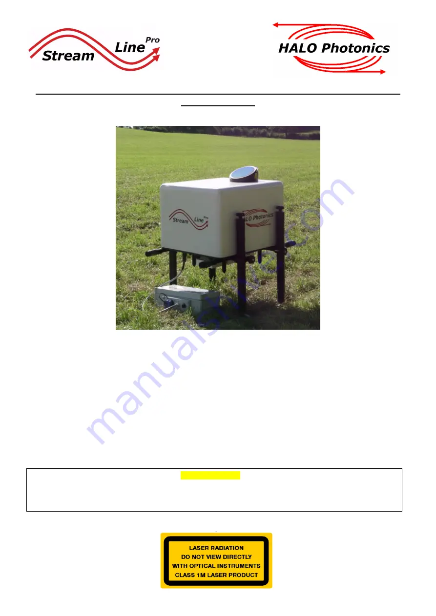
Halo Photonics Stream Line Pro Scanning Doppler Lidar system - Hardware and 

Software Guide. 


Our modular, autonomous, turn-key, pulsed Doppler Lidar systems were conceived to meet the need for remote 
sensing of motion and backscatter in the atmosphere. In this mode of operation, naturally occurring aerosols and 
clouds act as a distributed target and backscatter the transmitted pulses. The receiver detects the Doppler shift 
brought about by the motion of the distributed targets and therefore the line-of-sight component of their velocity. The 
novel optical technology employed and the design approach have led to a new class of eye-safe (Class 1M), high 
performance Lidar exhibiting exceptional stability which is compatible with a continuous and unattended mode of 
operation. Typical applications include boundary layer wind profiling, plume dispersion, analysis of complex flows, 
cloud studies, cloud base measurements and gust and air quality monitoring. 
 
While every effort has been made to provide accurate and calibrated data products, HALO Photonics does not 
currently guarantee the calibration of the data in absolute terms.   
 
The system has been designed to be rugged and autonomous. Even so, the end user must respect the fact that the 
system is a precision optical instrument that must be treated with great care.


The laser emission from the antenna is in the class 1M category. The responsibility for ensuring suitable safety 
procedures and operating modes lies entirely with the end user. HALO Photonics does not accept any 
responsibility for issues relating to the field deployment of the equipment and propagation of the beam in the 
atmosphere. 

Summary of Contents for Stream Line Pro

Page 1: ...ith a continuous and unattended mode of operation Typical applications include boundary layer wind profiling plume dispersion analysis of complex flows cloud studies cloud base measurements and gust a...

Page 2: ...ed The StreamLine user forum may be able to help with advising which software has worked successfully on other systems For remote connection to the Internet we would advise the use of SIM based modems...

Page 3: ...to be observed at all times The Lidar should be sited in such a way as to minimise the amount of heat generated by close surfaces such as tarmac or sunlight falling on it The temperature specification...

Page 4: ...coordinates 9 1 3 VAD scans 9 1 4 Wind profile scans 9 1 5 User defined scan file 9 1 6 Creating a custom scan file 9 2 Main control software 9 2 1 Real time data display 9 2 2 Data logging 9 2 3 Dat...

Page 5: ...nd 2A for UPS module Aux output line to blower 1 spare desiccant cartridge in a sealed bag 1 cable to connect the air blower to the Aux connector on the UPS unit optional 1 input connector for the UPS...

Page 6: ...ropriate manual handling health and safety guidelines The transit case consists of 3 separate pieces The Lidar is packed fully assembled Remove the top section and set it to one side The Lidar will no...

Page 7: ...ot attached They prevent the weight of the Lidar being taken by the cooling aggregate mounted on the underside of the main base plate which would cause damage The feet should all be roughly in the cen...

Page 8: ...ironment The Lidar will ship with an optional UPS module that has the correct connections for input to the Lidar The Lidar software when running will measure the input voltage to the UPS and if a powe...

Page 9: ...n it and it will need to be pulled out when unscrewed because it has an O ring seal that will prevent it from easily coming apart Recommended PSU for connection to the 24V DC input power protection mo...

Page 10: ...inlet coming from the power supply module F 1 10A 5x20mm fuse for the Lidar circuit F 2 10A 5x20mm fuse for the heaters and the thermo electric cooler TEC circuit if fitted There are 5 small LEDs clo...

Page 11: ...ion The connector may be plastic or metal type The metal type still has an orientation arrow but it won t be painted Ensure that the connector locks into place when interfacing The connector may need...

Page 12: ...mo switch which will enable the heater during temperatures lower than approximately 5 C The fan operation is via the blue button The blower unit is secured onto the back of the window mount with screw...

Page 13: ...mperature option If either of these options is fitted the heat exchanger fans will be on all of the time and soon after power is applied to the Lidar The cooling circuit is not covered by the UPS unit...

Page 14: ...pairs one end or one side at a time Turn the adjustment knobs clock wise looking from above to retract the leg and counter clock wise to extend The pitch and roll sensor has a resolution of 0 1 degre...

Page 15: ...nimise the heat generated underneath the Lidar from direct sunlight a turfed area is ideal Ambient temperatures quoted in the temperature specification of the Lidar are with respect to the air enterin...

Page 16: ...and running the client part of the remote access software found at this address http www halo photonics com rpcsetup exe During installation you will need to choose to install just the client part To...

Page 17: ...nnect to the Lidar using method 1 or 2 as above so that the IP assigned to the relevant LAN connection can be observed This IP address can then be used to connect to the system Once the appropriate IP...

Page 18: ...the problem persists follow this procedure The first time that a connection is made the following screen is displayed Choose the View screen option to view the desktop display of the Lidar PC The sof...

Page 19: ...he right and the local PC on the left Transfer via this method will be at the connection speed of the LAN If the Lidar PC is taking data then the transfer will be slowed down Be careful not to transfe...

Page 20: ...main control software Double click the icon to load and run The scan schedule can be altered during normal control software operation covered later and is also accessible from the desktop at any time...

Page 21: ...up the VAD scan The Repeat number represents the number of minutes between each start of successive scan executions The minimum repeat number available will be roughly equal to the total duration tim...

Page 22: ...mLine Pro systems excluding XR versions have electronic focus This feature will allow a focus to be selected for each scan type in the schedule The series of lines in the graph below show the effect t...

Page 23: ...onsisting of 8 rays at 75 degrees elevation from horizontal with 45 degrees in azimuth between them The first ray would be at 0 degrees in azimuth the next at 45 degrees and so on After the VAD scan i...

Page 24: ...pop up Once loaded the approximate scan duration number of points etc will be displayed The file that has been selected will not be over written by the schedule software instead it creates a new file...

Page 25: ...resents Many files can be produced and saved using this method Scan files can be loaded from any location but are stored in the directory C Lidar System Scan parameters after they have had the correct...

Page 26: ...panel should turn green if the system is ok If a failure occurs then the software may stop and an appropriate message should appear in the System information box Allow around 20 seconds for the tests...

Page 27: ...ity 7 55 PIN 8 26 Roll 0 20 Pitch 0 01 Started 10 01 11 16 32 16 Each time the software is started another set of parameters are saved to the campaign file Lat Long and Height highlighted above are on...

Page 28: ...system experiences an over temperature state low disk space a power cut auto starting after a power cut and also a general daily status A pop up window will appear whenever the Email alerts button ch...

Page 29: ...position changes from the OFF position to the ON position during system setup After the required settings have been selected and the Accept settings button has been pressed the current settings will b...

Page 30: ...not the raw data file The Colour display parameters are purely for display and don t alter the logged data in any way The Background file This file is taken while the system is running normally but w...

Page 31: ...drive may reduce acquisition speed Data logging directory structure Data are logged using the following directory structures C Lidar Data Proc yyyy yyyymm yyyymmdd for processed data C Lidar Data Raw...

Page 32: ...9E 6 8 0 2397 1 029193 1 695600E 6 Typical VAD data file header and data format Filename C Lidar Data Proc 2010 201009 20100909 VAD_06_20100909_165213 hpl System ID 00 Number of gates 320 Range gate l...

Page 33: ...r repeat time in seconds and the number of seconds until the next repeat The C C button next to any currently displayed scan can be pressed to continuously cycle the chosen scan If multiple C C button...

Page 34: ...its data are logged to a file that is stored in the monthly directory in the processed data directory C Lidar Data Proc yyyy yyyymm system_parameters_SystemID_yyyymm txt An example file showing date t...

Page 35: ...eights first then successive data points giving height AGL wind direction and horizontal wind speed 200 0 0 00 0 00 48 229 55 14 40 96 232 82 11 44 144 230 20 11 44 192 228 82 14 02 240 232 80 14 53 2...

Page 36: ...10 Shutting down Back to contents Double click the Shutdown icon to load up the software Description This module will shut down the internal systems of the Lidar in a controlled manor and will also s...

Page 37: ...reason to suspect that the readings are false please contact Halo The Trigger LED is red The system should not start up in this situation Try starting the software again The Acquisition card LED is re...

Page 38: ...or so If the LED is flashing then check your network settings and if correct try a repair connection or the Lidar firewall might need to be turned off if the connecting PC is running Win7 If the RJ45...

Page 39: ...below provided the fractional coverage of the clear aperture is not too high The output window has a hard anti reflection coating on the outer surface The coating is reasonably robust but should it be...

Page 40: ...will be set to GMT The Lidar has a time synchronisation program installed loads and runs at startup that will keep the computer clock synchronised to a network time server The PC needs to have Interne...

Page 41: ...If your system doesn t have GPS then the option is not available but can be retro fitted if the system is returned Selecting hourly GPS time synchronisation This is chosen at set up time or if the Ch...

Page 42: ...d they are tab delimited with a carriage return character following the last one 081369 pr d 0 500 70 002 3 00 0 15 0 17 0 15 0 08 0 08 0 32 18 42 The ray s header contains information separated by ch...

Page 43: ...ternal temperature of the Lidar at 25 C It will offer both active heating and cooling and draw an extra 130W of power when fully cooling and an extra 60W when heating System fitted with the extended t...

Page 44: ...o data files will be larger Raw data will be unaffected Doppler estimations may be less accurate than for longer gates Higher down range resolution Long gates 40m Fewer gates will be returned so proce...

Page 45: ...r the RJ45 X connection are set to the default IP Address 192 168 0 1 Subnet mask 255 255 255 0 Default gateway 192 168 0 1 The Remote access software that the system came with is able to run at start...

Reviews: