HAKO Sweepmaster P900 R, Operating Manual
The HAKO Sweepmaster P900 R is a top-of-the-line cleaning machine designed to effortlessly sweep and maintain any space. Ensure optimal use of this powerful device with our comprehensive operating manual, available for free download at manualshive.com. Obtain the necessary instructions and get the most out of your cleaning experience today.
Share
Download


Reviews:
No comments
Related manuals for Sweepmaster P900 R

STRATO-CHARGED EBZ4800
Brand: Zenoah Pages: 8

EBZ5100Q
Brand: Zenoah Pages: 56

CLUBBLOWER
Brand: MAGIC FX Pages: 20

850 Super Blower/Vac
Brand: Toro Pages: 8
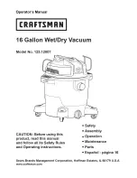
125.12007
Brand: Craftsman Pages: 30

E663G
Brand: MTD Pages: 28

LS 3019
Brand: Okay Pages: 32

94578
Brand: Gude Pages: 104

94395
Brand: Gude Pages: 56

W50063
Brand: Performance Tool Pages: 8

Sweeper
Brand: Alto Pages: 12

E-LS-2800/50 2
Brand: Lux Tools Pages: 72

89041
Brand: Power Craft Garden Pages: 50

78153
Brand: Power Craft Garden Pages: 22

89033
Brand: Power Craft Pages: 49

913ML2-S
Brand: FUJII Pages: 70

BL6500HA
Brand: Maruyama Pages: 20

EBZ5000Q
Brand: RedMax Pages: 36


