


Reviews:
No comments
Related manuals for Scrubmaster B25
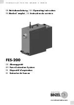
FES-200
Brand: Abicor Binzel Pages: 100

Nautilus MX3-500HE
Brand: Hydro-Force Pages: 57

6FN
Brand: M-system Pages: 2

64P8 Series
Brand: Bissell Pages: 12

Scrubmaster B30
Brand: HAKO Pages: 54

CM-5.3 Cyclone
Brand: parktool Pages: 2

73-501
Brand: Ace Pages: 13

ruby 48 blt
Brand: Floorpul Pages: 16

PRIME PRO kit
Brand: Livington Pages: 8

NGS 1000
Brand: Imac Pages: 4

FSL100
Brand: Full Spectrum Laser Pages: 12

ESE201A-W-HV
Brand: Enviroflex Pages: 5

CCRRSS2288
Brand: BETCO Pages: 91

AT170E
Brand: Axminster Trade Pages: 32

RA 330 IBC
Brand: Cleanfix Pages: 17


