Haivision MB21, Installation Manual
The Haivision MB21 is a state-of-the-art media device that seamlessly delivers high-quality audio and video content. To help you easily set it up, we offer a comprehensive and user-friendly Installation Manual for free download. Simply visit our website manualshive.com and get the manual you need to unlock the full potential of your MB21.
Share
Download


Reviews:
No comments
Related manuals for MB21

H5
Brand: HDPlex Pages: 34

SC113TQ-563CB
Brand: Supero Pages: 80

MT850A
Brand: Black Box Pages: 7
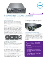
PowerEdge C5000
Brand: Dell Pages: 2

1269
Brand: Racal Instruments Pages: 170

SC847 Series
Brand: Supero Pages: 188

Hummer Vault
Brand: nox Pages: 13

HUMMER NEXUS
Brand: nox Pages: 13

EN-898X
Brand: Enlight Pages: 45

MT45 2019
Brand: freightliner Pages: 89


