


Reviews:
No comments
Related manuals for HSP 7

Oscar
Brand: Faber Pages: 15

PS35-C
Brand: Quadra-Fire Pages: 32

SANTAFE-MBK
Brand: Quadra-Fire Pages: 32
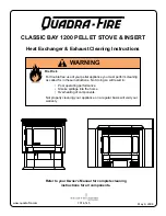
CLASSIC BAY 1200
Brand: Quadra-Fire Pages: 4
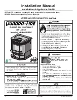
CB1200M-MBK
Brand: Quadra-Fire Pages: 28

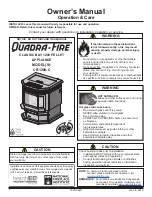
CLASSIC BAY 1200
Brand: Quadra-Fire Pages: 28
CLASSIC BAY 1200
Brand: Quadra-Fire Pages: 40

21M-ACC-AU
Brand: Quadra-Fire Pages: 20

Garnet
Brand: Quadra-Fire Pages: 12

Hotspur 5
Brand: Broseley Pages: 38

SI 1100FST
Brand: Warmington Pages: 12

ET 3031
Brand: ECG Pages: 60

Telford Inset 5 MKII
Brand: Hunter Stoves Pages: 25

HSP 6 537.08-WT RLU/PGI
Brand: HAAS + SOHN Pages: 28

Countyside
Brand: Country Flame Pages: 1

D-17
Brand: Daiwa Pages: 17

WF32
Brand: Westfire Pages: 4

EcoFire IDRO
Brand: Palazzetti Pages: 140


