H3C WA2210-AG, Installation Manual
The H3C WA2210-AG is a high-performance wireless access point designed to provide fast and reliable connectivity. For easy installation and setup, make sure to download the free Installation Manual from our website. This manual will guide you through the process step by step to ensure smooth operation of your device.
Share
Download


Reviews:
No comments
Related manuals for WA2210-AG

Rangebooster N 650 Access Point DAP-1353
Brand: D-Link Pages: 67

DWL-1000AP
Brand: D-Link Pages: 8
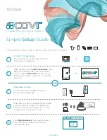
COVR-2202
Brand: D-Link Pages: 2

DAP-1155
Brand: D-Link Pages: 3

Air Premier DAP-2695
Brand: D-Link Pages: 39
AirPlus DI-714P+
Brand: D-Link Pages: 5
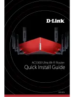
AC5300
Brand: D-Link Pages: 12
SharePort DIR-825
Brand: D-Link Pages: 20
Express EtherNetwork DI-604
Brand: D-Link Pages: 49

PAN1026A
Brand: Panasonic Pages: 20

WF-2000 Series
Brand: ICP DAS USA Pages: 8

W45AP
Brand: IP-COM Pages: 2

Wifi bridge
Brand: jbmedia Pages: 6

EZ-GO
Brand: E-ZY Pages: 8

WAC6500 Indoor Series
Brand: ZyXEL Communications Pages: 2

RangeMax NEXT WNR834A
Brand: NETGEAR Pages: 106

AP-AG-AT-02
Brand: Universal Scientific Industrial Co. Pages: 19

LP-8096
Brand: Loopcomm Pages: 66


