Guzauski-Swist GS-3a, User Manual
The Guzauski-Swist GS-3a User Manual is available for free download at manualshive.com. This comprehensive manual provides step-by-step instructions and settings to optimize your experience with the GS-3a audio processor. Access this essential manual now to enhance your audio production skills and achieve professional-grade results effortlessly.
Share
Download


Reviews:
No comments
Related manuals for GS-3a
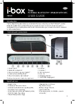
Trax
Brand: i-box Pages: 4

BTS21
Brand: Ebode Pages: 64

KF760
Brand: EAW Pages: 31

ZEB-CLAW 4
Brand: Zebronics Pages: 10

GlaXfi-HH22
Brand: GAIT Pages: 2

Sirocco 530
Brand: Cambridge Audio Pages: 6

2.2 Series II
Brand: Bose Pages: 9

Energy XD2
Brand: iDance Pages: 36

VT-4000W
Brand: V-TAC Pages: 3
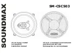
SM-CSC503
Brand: SoundMax Pages: 15

Three-way Passive System Screen 4P
Brand: Martin Audio Pages: 1

BTS-639
Brand: Powerhouse Pages: 9

PSP1
Brand: Prestigio Pages: 2
GTx 352 DE
Brand: Blaupunkt Pages: 11

MBU5
Brand: DLS Pages: 2

GXR-12
Brand: Lynx Pages: 14

Pulse 4
Brand: JBL Pages: 30

EP-2001G series
Brand: Senrun Pages: 20


