


Guilin Feiyu Electronic Technology Co.,Ltd
Guilin Feiyu Electronic Technology Co.,Ltd http://www.feiyudz.cn Tel:0773-5815749
1
FY3-ZT Autopilot
User Agreement
This product belongs to sensitive control items of PRC government regulation. Users have to
pay all the responsibility for purchase and use of all the products. For this product, our company
will not pay any responsible for the risk and obligation during debugging and uses. (For any direct,
indirect or the third parties losses which caused by the fault diagnosis of the air and air crash).
Please read this Instruction carefully before you use FY-3ZT Autopilot ,if there is any
problem you are not clear , please contact us ,we will give you satisfactory reply at our first time .
For any improperly obtained product or abnormal usage, our company will pay no responsibility
and service.
Our company reserves the right to modification the terms and conditions, change or terminate
the offer without any prior notices.
The Agreement will become effective automatically since users purchased this product.
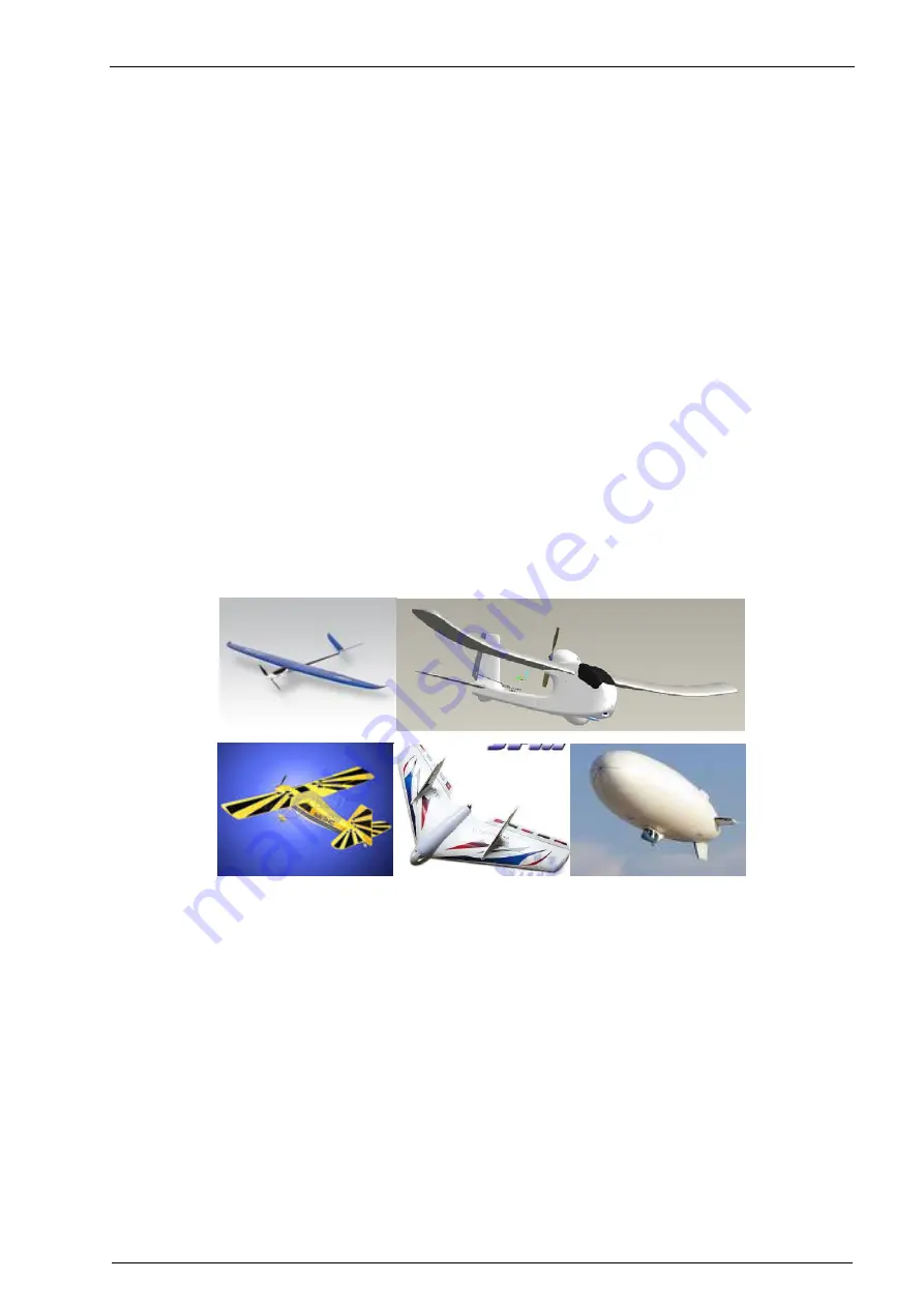
Typical Applications
Automatic navigation and piloting of Regular, V end, elevator and aileron, without ailerons and
other layout of small and medium size aircraft.
Automatic navigation and driving of all kinds of airship.
Macro Feathers
FY3-ZT provide high-precision attitude through to use 32 ARM7microprocessors, integrate
GPS receiver, three-axis MEMS gyro, three-axis accelerometers, pressure altimeter, inertial
strapdown attitude algorithm and combined with Kalman digital filtering and data fusion
algorithms .
Integrated UBLOX 5th generation GPS receiver, 4Hz output, 35 seconds fast positioning time
and accuracy of 2.5 meters CEP.
50HZ inner attitude control, 4HZ outer navigation control.
Multi-channel mixed-control output can be easily adjusting the mixed-control. Including
normal layout none mixed rudder control navigation, elevator and aileron rudder navigation,
elevator and aileron mixed-control navigation, none ailerons rudder navigation. And can
adjust the neutral position in real-time.
Three kinds of control modes:
Manual remote control, Auto balance remote control and
Automatic
navigation control.


