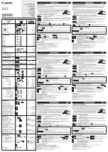
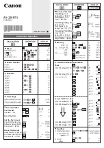
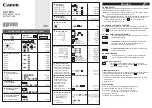
GSS HDTA 614 T ASI, Assembly & Instruction Manual
The GSS HDTA 614 T ASI is a high-quality product that comes with an Assembly & Instruction Manual. This comprehensive manual provides step-by-step guidance on how to assemble and operate the product effectively. You can download this manual for free from our website, making it easily accessible to all users.
Share
Download


Reviews:
No comments
Related manuals for HDTA 614 T ASI
F-789SGA
Brand: Canon Pages: 35
F-788dx
Brand: Canon Pages: 2
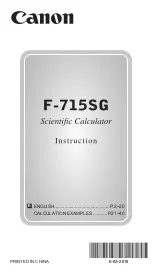
F-715SG
Brand: Canon Pages: 20
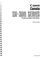
Canola SX-300 series
Brand: Canon Pages: 60
KS-1200TS
Brand: Canon Pages: 2
AS-220RTS
Brand: Canon Pages: 2
AS-1200
Brand: Canon Pages: 2

VeCOAX MicroMod-2
Brand: PVI Pages: 40

CS-2635E
Brand: Sharp Pages: 13

Compet Elsi-Mate EL-120
Brand: Sharp Pages: 14

COMPET-221 CS-221A
Brand: Sharp Pages: 24

COMPET QS-2130
Brand: Sharp Pages: 24

COMPET CSA-2130
Brand: Sharp Pages: 21

Compet 17
Brand: Sharp Pages: 17

COMPET-23
Brand: Sharp Pages: 36

Compet CS-2122H
Brand: Sharp Pages: 37

CS-1194H - 10 Digit Desktop Display
Brand: Sharp Pages: 48

CS-2635H
Brand: Sharp Pages: 48


